
In my years of experience in the foundry industry, I have observed that slag inclusion defects remain a persistent and costly issue in casting production. Slag inclusion, often referred to as dross or non-metallic inclusion, occurs when slag particles are entrapped within the metal matrix during the pouring and solidification processes. These defects can severely compromise the mechanical properties, pressure tightness, and overall integrity of cast components, leading to high rejection rates, especially in precision applications like machine tool hydraulic parts. The formation of slag inclusion is multifaceted, stemming from factors in melting, pouring operations, molding practices, and the design of gating systems. This article delves into a comprehensive, first-person perspective on the strategies I employ to prevent and control slag inclusion, emphasizing practical measures, theoretical underpinnings, and systematic approaches. I will integrate tables and formulas to summarize key concepts, ensuring a deep, technical exploration aimed at exceeding 8000 tokens in length.
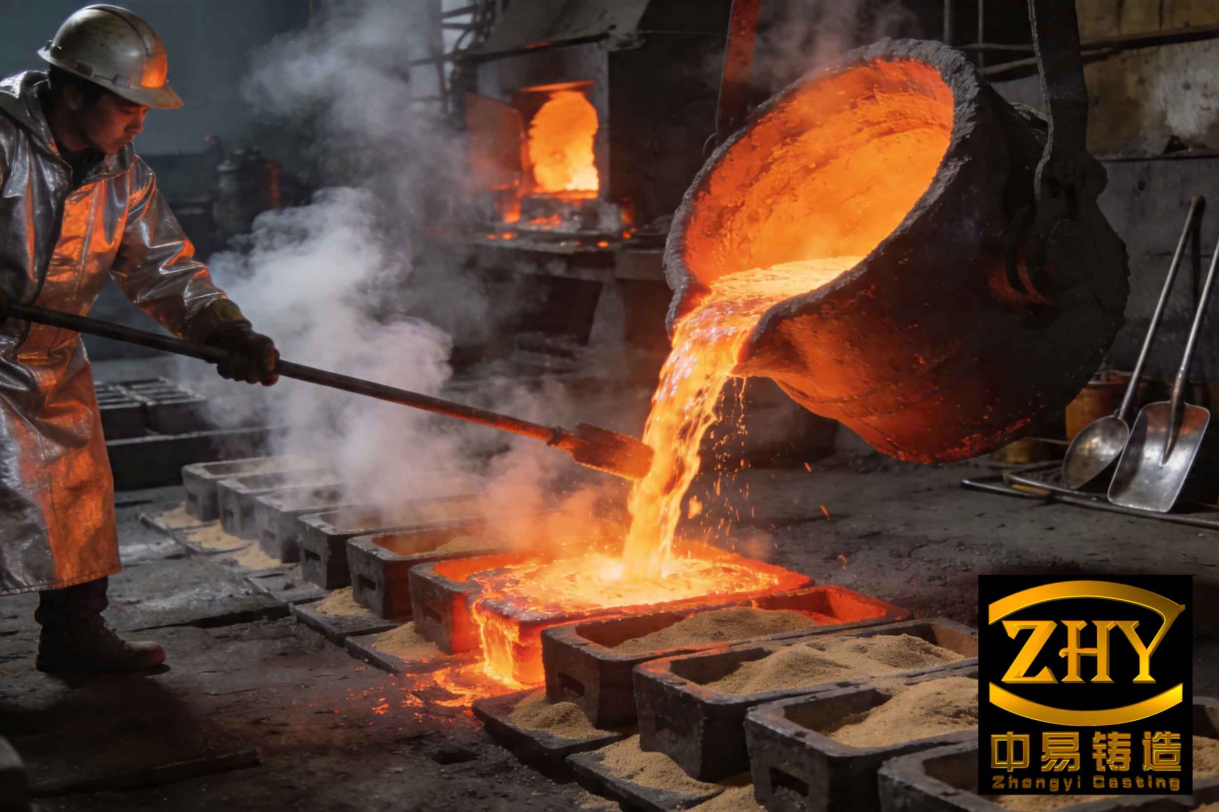
The visual representation above illustrates typical slag inclusion defects in castings, highlighting the detrimental impact on surface and internal quality. Preventing such slag inclusion requires a holistic approach, starting from the furnace and extending to the final casting. In my practice, I treat slag inclusion as a dynamic adversary that must be managed at every stage. The core principle is to separate slag from molten metal before it enters the mold cavity, utilizing physical, chemical, and hydrodynamic methods. Throughout this discussion, I will repeatedly emphasize the term ‘slag inclusion’ to reinforce its centrality in foundry quality control.
Slag Inclusion Control During Melting Operations
Melting is the first line of defense against slag inclusion. During iron melting, particularly in cupolas, a viscous slag composed of coke ash, sand, and eroded refractory materials forms. If not adequately removed, this slag inclusion source can be carried into the ladle and subsequently into the mold. My approach involves proactive slag formation and removal.
Firstly, I ensure proper fluxing agents are added. Limestone (CaCO3) is commonly used as a slag conditioner. Upon heating, it decomposes: $$CaCO_3 (s) \rightarrow CaO (s) + CO_2 (g)$$ The calcium oxide (CaO) then reacts with acidic oxides in the slag (e.g., SiO2, Al2O3) to form lower-melting-point, fluid slag compounds: $$CaO + SiO_2 \rightarrow CaSiO_3 (l)$$ This fluid slag can easily separate from the molten iron due to density differences. The effectiveness of this reaction influences the final slag inclusion propensity. I monitor the basicity index of the slag, often defined as: $$BI = \frac{%CaO + %MgO}{%SiO_2}$$ A basicity index between 1.0 and 1.5 typically promotes good fluidity, facilitating slag tapping.
Secondly, maintaining high molten metal temperature is critical. Temperature affects slag viscosity (\(\eta_s\)) and the buoyancy-driven separation velocity of slag particles. The terminal velocity (\(v_t\)) of a spherical slag particle rising through molten metal can be approximated by Stokes’ law: $$v_t = \frac{2 g r^2 (\rho_m – \rho_s)}{9 \eta_m}$$ where \(g\) is gravitational acceleration, \(r\) is the slag particle radius, \(\rho_m\) and \(\rho_s\) are the densities of molten metal and slag respectively, and \(\eta_m\) is the dynamic viscosity of the molten metal. Higher metal temperature reduces \(\eta_m\), thereby increasing \(v_t\) and enhancing slag flotation and removal. Inadequate temperature leads to viscous slag that is difficult to tap, increasing the risk of slag inclusion.
I implement regular and timely slag tapping from the forehearth or receiver. The frequency is based on melt rate and slag accumulation models. A delay in tapping allows slag to be drawn into the tap stream. The table below summarizes key melting parameters I control to minimize slag inclusion sources.
| Parameter | Target Range / Practice | Effect on Slag Inclusion |
|---|---|---|
| Flux Addition (Limestone) | 1.5-3.0% of metal charge | Promotes fluid, separable slag; reduces slag inclusion risk. |
| Metal Tap Temperature | > 1500°C for gray iron | Lowers slag & metal viscosity, improves slag flotation and separation. |
| Slag Basicity Index (BI) | 1.0 – 1.5 | Ensures optimal slag fluidity for easy removal. |
| Slag Tapping Frequency | Every 20-30 minutes of continuous melting | Prevents slag buildup and carryover into the ladle. |
| Furnace Lining Condition | Regular inspection and maintenance | Minimizes refractory erosion, a source of slag inclusion particles. |
By rigorously controlling these factors, I significantly reduce the primary source of slag inclusion before the metal even leaves the furnace.
Slag Inclusion Control During Pouring and Ladle Treatment
Despite best efforts in melting, some slag inclusion materials invariably transfer to the pouring ladle. Therefore, secondary removal in the ladle is essential. My procedure involves a two-step process: slag aggregation and physical removal.
Immediately after receiving the metal, I apply slag coagulants or collectors to the ladle’s metal surface. These materials, such as expanded perlite or volcanic ash, partially melt and envelop the dispersed slag particles, aggregating them into a cohesive, easily removable mass. The mechanism involves surface wetting and adhesion. The effectiveness depends on the coagulant’s properties and the metal temperature. For instance, rice husk ash, sometimes used, provides insulation but has lower aggregation efficiency for certain slag types compared to perlite.
The ‘skimming’ or ‘slag-off’ operation must be thorough. I use preheated rakes or bars to gently but completely remove the aggregated slag layer. Any residual slag inclusion material left in the ladle is a direct threat. During pouring, I always employ a slag stopper or a worker dedicated to ‘slag watching’ to block slag at the lip of the ladle. This manual intervention is crucial, especially for smaller batches.
A critical practice is maintaining a continuous pour. Interruptions during pouring cause the sprue to partially empty, breaking the siphon effect and destroying the slag-trapping capability of the pouring basin and gating system. This can allow trapped slag to be drawn into the mold, creating slag inclusion defects. The flow rate \(Q\) should be steady and is often calculated based on the mold cavity volume \(V\) and desired fill time \(t\): $$Q = \frac{V}{t}$$ A consistent \(Q\) helps maintain a positive pressure head in the sprue, aiding slag flotation within the gating system itself.
I also consider the ladle design. Ladles with a deep, well-defined pour basin and a tapered spout promote smoother, non-turbulent flow, reducing the re-entrainment of any surface slag inclusion. The table below contrasts different ladle treatment practices.
| Practice | Tool/Material | Advantage | Limitation |
|---|---|---|---|
| Slag Aggregation | Expanded Perlite | Excellent slag wetting & cohesion; widely effective. | Adds minor cost; requires dry storage. |
| Slag Aggregation | Rice Husk Ash | Good insulation; locally available in some regions. | Moderate slag collection efficiency; can be inconsistent. |
| Slag Skimming | Preheated Steel Rake | Direct physical removal; immediate visual confirmation. | Labor-intensive; skill-dependent; causes some heat loss. |
| Slag Watching During Pour | Slag Stopper Rod | Prevents last-moment slag entry; essential for critical castings. | Requires constant attention and skilled operator. |
These ladle-stage measures form a vital barrier against slag inclusion, complementing the melting operations.
Slag Inclusion Control Through Molding and Gating System Design
The gating system is not merely a conduit for metal; it is the final and most sophisticated filter for slag inclusion. My design philosophy prioritizes slag separation through controlled fluid dynamics. Turbulence is the enemy, as it can break up and disperse slag particles, making them harder to trap.
The primary elements are the pouring basin, sprue, sprue well, runner (or cross gate), and ingates. Each has a specific role in mitigating slag inclusion. The pouring basin should be designed to minimize vortex formation. A vortex can suck surface slag directly into the sprue. I often use basins with a dam or weir. The sprue should be tapered to prevent aspiration and maintain a choke effect. The sprue well acts as an initial momentum absorber and slag trap.
The runner is the main workhorse for slag removal. I design runners with a trapezoidal cross-section, taller than wide, to promote a calm, laminar flow in the lower portion while allowing slag to float and be trapped in the upper portion. The first ingate should be located at a sufficient distance from the sprue well. This distance \(L_{min}\) is calculated to provide adequate time for slag flotation: $$L_{min} = v_t \cdot t_{run}$$ where \(t_{run}\) is the time metal flows in the runner before reaching the first ingate. Ingates are typically flat and wide (flattened trapezoid) to create a high velocity, narrow stream that draws metal from the lower, cleaner part of the runner—a principle known as the “skim gate” effect.
Ingate placement is crucial. Symmetrical placement helps balance flow and prevents dead zones where slag inclusion might settle. The total cross-sectional area ratios of the gating system (sprue : runner : ingates) follow proven rules, like the pressurized (e.g., 1 : 2 : 1.5) or non-pressurized systems, depending on the alloy and casting geometry. The goal is to achieve a slow fill in the mold cavity itself after the runner has done its slag-removal job.
To quantify the slag trapping efficiency of a runner, I sometimes model the required runner length based on the worst-case slag particle size. Assuming Stokes’ law applies in the runner channel, the time \(t_f\) for a particle to float to the top of the runner channel of height \(H_r\) is: $$t_f = \frac{H_r}{v_t}$$ The runner must be long enough so that the metal residence time exceeds \(t_f\) for the target particle size. This is a fundamental check in my design process to prevent slag inclusion.
| Gating Element | Design Feature | Function in Slag Inclusion Control |
|---|---|---|
| Pouring Basin | Dam/Weir, Large Surface Area | Prevents vortex, allows initial slag floatation and retention. |
| Sprue | Tapered (Atop > Abottom) | Prevents aspiration of air and slag; maintains pressurized flow. |
| Runner (Cross Gate) | High Aspect Ratio Trapezoid, Length > 5x Height | Provides calm, stratified flow; slag floats and is trapped in upper zone. |
| Ingates (Gates) | Flattened Trapezoid, located at runner bottom | Draws clean metal from below the slag layer; minimizes disturbance. |
| Runner Extension / Blind End | Length >= 20% of total runner length | Traps the first, most contaminated metal and slag, preventing backflow. |
By meticulously designing these elements, I create a gating system that actively filters out slag inclusion, protecting the mold cavity.
Advanced Gating Systems for Critical Slag Inclusion Prevention
For castings where even minute slag inclusion is unacceptable, I employ specialized gating systems with enhanced slag separation capabilities. These systems often incorporate centrifugal force or stepped flow restrictions.
1. Whirl Gate or Centrifugal Separator: This is one of my most effective tools against slag inclusion. A whirl gate is a circular chamber placed between the runner and ingates. Metal enters tangentially, creating a rotating flow. The centrifugal acceleration \(a_c\) is given by: $$a_c = \frac{v_t^2}{r_c}$$ where \(v_t\) is the tangential velocity and \(r_c\) is the chamber radius. Slag particles, being less dense, are forced toward the center of the vortex and upward, collecting in a central dome. The clean metal exits from a radial or tangential port at the bottom or periphery. The separation efficiency \(\eta_{sep}\) can be high, often above 95% for particles above a critical size. I use this for important, complex castings.
2. Step-Gating or Choke Systems: These include systems like the strainer core gate or throttled runner. They create a localized restriction (choke) that increases velocity, promoting turbulence intentionally at a point where slag can be trapped in a subsequent enlarged chamber. The Bernoulli principle is at play: $$P + \frac{1}{2} \rho v^2 + \rho g h = \text{constant}$$ A reduction in cross-sectional area increases velocity \(v\), decreasing pressure \(P\), which can help dislodge slag particles, but the design must ensure they are caught in a downstream trap.
3. Runner with Multiple Slag Traps or Baffles: Incorporating enlarged chambers or dams along the runner creates low-velocity zones where slag inclusion particles can settle or float out of the main stream. These are simpler to implement than whirl gates.
4. Combination Systems with Integrated Riser: For thick-section castings requiring feeding, I often combine a whirl gate with a riser. The whirl gate acts as both a slag separator and a hot metal reservoir for feeding. This improves yield while solving the slag inclusion problem. The design must satisfy both the feeding requirements (using modulus method, e.g., \(M_{riser} > 1.2 M_{casting}\)) and the fluid dynamics for slag separation.
The choice among these depends on the casting geometry, production volume, and required quality level. The table below provides a comparative overview.
| System Type | Mechanism | Slag Inclusion Removal Efficiency | Best For |
|---|---|---|---|
| Standard Skim Gate (Trapezoidal Runner) | Buoyancy & Stratified Flow | Moderate (60-80%) | General engineering castings, high-volume production. |
| Whirl Gate (Centrifugal Separator) | Centrifugal Force | Very High (>90%) | Critical castings (hydraulic, valve bodies), batch production. |
| Step-Gating / Choke System | Pressure/ Velocity Change, Impingement | High (70-85%) | Castings with limited space for gating. |
| Runner with Slag Trap Chambers | Settlement & Buoyancy in Low-flow Zones | Moderate to High (65-85%) | Medium to large castings, simpler fabrication. |
| Integrated Whirl Gate-Riser | Centrifugal Force + Feeding | Very High (>90%) & Provides Feeding | Thick-section castings requiring soundness and cleanliness. |
In my practice, for a lathe bed or a pump housing, I might opt for a whirl gate. For a simpler bracket, a well-designed standard skim gate suffices. The key is to match the system’s capability to the slag inclusion risk level.
Complementary Practices and Overall Strategy
Beyond the core technical areas, I adhere to several complementary practices that collectively suppress slag inclusion. Mold and core coatings play a role; I use refractory washes that resist erosion and minimize sand inclusions, which can act as nucleation sites for or be mistaken for slag inclusion. Proper drying of molds and cores is essential to prevent gas evolution that can stir up slag particles.
Metal chemistry control is also part of the strategy. Elements like aluminum or high levels of silicon can form tenacious oxides that contribute to slag inclusion. I monitor and adjust composition to minimize oxide-forming tendencies. For example, in ductile iron, post-inoculation practices are controlled to minimize magnesium silicate slag formation.
Process monitoring and data analysis are integral. I maintain logs of melting parameters, slag tapping times, pouring temperatures, and defect maps for castings. Using statistical process control (SPC), I track the occurrence of slag inclusion defects. If a trend appears, I can trace it back to a specific variable, such as a drop in tapping temperature or a change in flux supplier.
The fight against slag inclusion is continuous. New alloys, higher performance requirements, and sustainability pressures drive innovation. I explore emerging technologies like advanced filtration ceramics in the gating system, real-time slag detection sensors in the launder, and improved flux compositions. The fundamental equations, however, remain guiding principles. For instance, optimizing the Rayleigh number for natural convection in a ladle during treatment can help mix in additives while allowing slag to float, but that’s a topic for another detailed discussion.
In conclusion, my first-hand experience confirms that preventing slag inclusion is not about a single magic bullet. It is a disciplined, multi-stage campaign. It begins with effective slag management in the melting unit (‘slag tapping’), continues with vigilant ladle treatment (‘slag skimming’ and ‘slag watching’), is engineered into the mold through intelligent gating design (‘slag trapping’), and is supported by robust process controls and complementary practices. Every foundry person must internalize that slag inclusion is a pervasive threat, but one that can be systematically defeated. By applying the principles and practices outlined here—from the Stokes’ law calculations for particle flotation to the centrifugal force in a whirl gate—I consistently achieve castings with minimal slag inclusion, ensuring high quality, reliability, and customer satisfaction. The journey to eliminate slag inclusion is ongoing, but with a scientific approach and meticulous execution, it is a winnable battle.
To further solidify the concepts, let’s consider a mathematical summary of the key forces acting on a slag particle, which dictates its behavior and our strategies:
The net upward force \(F_{net}\) on a slag particle in molten metal is the difference between buoyancy \(F_b\) and gravity \(F_g\), adjusted by drag \(F_d\) when moving: $$F_{net} = F_b – F_g – F_d = \frac{4}{3}\pi r^3 (\rho_m – \rho_s) g – 6\pi \eta_m r v$$ For steady-state rising velocity \(v_t\), \(F_{net}=0\), leading back to Stokes’ law. Our entire endeavor in slag inclusion control—from using fluxes to reduce \(\eta_m\) and \(\rho_s\), to designing runners that maximize the time for \(v_t\) to act, to creating centrifugal forces that mimic enhanced \(g\)—is essentially about manipulating the terms in this fundamental equation to our advantage. Therefore, a deep understanding of these physical principles is indispensable for anyone serious about conquering the challenge of slag inclusion in castings.