
In the production of six-cylinder engine blocks using the coated sand iron mold casting process, blow hole defects have been a persistent challenge affecting product quality and yield. These blow hole defects typically manifest as surface or subsurface voids in critical areas like the cylinder top or water jacket surfaces, leading to significant scrap rates. This article details the systematic approach we adopted to mitigate these blow hole defects, focusing on modifications to gating systems, venting mechanisms, and structural optimizations. Through rigorous implementation and analysis, we achieved a substantial reduction in blow hole defect rates, enhancing the overall reliability of the casting process.
Blow hole defects arise primarily from entrapped gases during solidification, often due to inadequate venting or turbulent metal flow. In our initial production runs, we observed that blow hole defects accounted for over 40% of scrap parts, severely impacting efficiency. The defects were identified as invasive types, where gases from the sand cores infiltrated the molten metal before solidification. Key factors included insufficient venting paths, prolonged pouring times causing excessive core heating and gas generation, and flow turbulence within the mold cavity. To address this, we analyzed the root causes and developed targeted interventions, which are elaborated in the following sections.
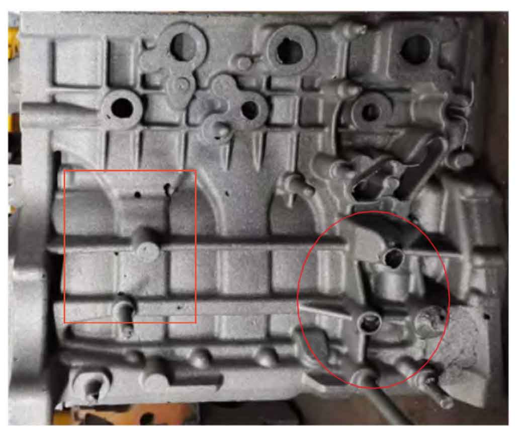
Our casting setup involved a single-piece mold configuration for the six-cylinder block, with dimensions of approximately 1203 mm × 403 mm × 616 mm and a weight of 513.5 kg. The thin-walled sections (down to 5 mm) exacerbated the risk of blow hole defects, as rapid gas entrapment could occur in these regions. Initial trials revealed that the original mold design, adapted from resin sand methods, lacked optimized venting. For instance, vent pins were misaligned or absent in core head areas, leading to gas buildup and subsequent blow hole defects. The figure below illustrates typical blow hole defects observed on the casting surface:
Analysis indicated that during pouring, gases from the water jacket core were trapped, creating high-pressure zones that invaded the molten metal. Pouring times exceeding 45 seconds correlated strongly with increased blow hole defect incidence, as prolonged exposure allowed more gas generation from heated cores. Flow turbulence further aggravated this by creating air pockets. To quantify the relationship, we derived an empirical formula for blow hole defect formation rate. Let \( d \) represent the defect rate (as a percentage), \( t \) the pouring time in seconds, and \( k \) a constant based on mold conditions (e.g., core gas generation rate). The relationship is expressed as:
$$ d = k \cdot t^{1.5} $$
For our initial setup, \( k \) was approximately 0.15, leading to \( d = 41\% \) at \( t = 48 \) seconds. Reducing pouring time became a critical objective to suppress blow hole defects. Additionally, the gas pressure \( P_g \) in the core head can be modeled using the ideal gas law, where \( n \) is moles of gas, \( R \) is the gas constant, \( T \) is temperature, and \( V \) is volume:
$$ P_g = \frac{nRT}{V} $$
High \( P_g \) forces gas into the metal, forming blow hole defects. Our interventions aimed to minimize \( P_g \) by enhancing venting and reducing gas accumulation.
Original Process Deficiencies and Blow Hole Defect Mechanisms
The initial mold design featured poorly positioned vent pins, with only a few installed away from core head centers, causing inefficient gas escape. This resulted in blow hole defects appearing consistently on upper surfaces after shot blasting or machining. We identified three main contributors to blow hole defects: (1) inadequate core venting leading to gas entrapment, (2) slow pouring times exceeding optimal thresholds, and (3) turbulent flow patterns that created air entrainment. Venting efficiency \( \eta_v \) was calculated as the ratio of effective vent area to total core head area, with initial values below 0.3, indicating severe limitations. The formula for venting efficiency is:
$$ \eta_v = \frac{A_v}{A_c} $$
where \( A_v \) is the vent area and \( A_c \) is the core head area. Low \( \eta_v \) directly correlated with higher blow hole defect rates.
Comprehensive Measures to Eliminate Blow Hole Defects
We implemented a multi-faceted strategy to tackle blow hole defects, focusing on gating system modifications, venting enhancements, structural reinforcements, and process controls. Each measure was designed to reduce gas entrapment and promote smoother metal flow.
Gating System Optimization
To accelerate pouring and minimize core heating, we increased the cross-sectional area of the ingates, transitioning from a closed to a semi-open system. This change reduced pouring time, directly lowering blow hole defect incidence. The original ingate dimensions were modified as follows: for the main core, the ingate size was enlarged from 33.5/34.6 mm × 8 mm to 33.5/33.4 mm × 10 mm (12 ingates total). For the outer mold bottom, it was changed from 50.2/47.7 mm × 7.5 mm to 50.2/46.9 mm × 9.5 mm (6 ingates). The new ingate area \( A_i \) increased by approximately 25%, calculated as:
$$ A_i = w \times h $$
where \( w \) is width and \( h \) is height. This expansion allowed faster metal entry, cutting pouring time from over 48 seconds to under 42 seconds at a molten metal temperature of 1420°C. The pouring time formula, based on flow rate, is:
$$ t = \frac{V}{Q} $$
where \( V \) is mold cavity volume (0.065 m³) and \( Q \) is flow rate. Higher \( Q \) from larger \( A_i \) reduced \( t \), suppressing blow hole defects.
| Component | Original Dimensions (mm) | Modified Dimensions (mm) | Area Increase (%) | Impact on Blow Hole Defect Rate |
|---|---|---|---|---|
| Main Core Ingates | 33.5/34.6 × 8 | 33.5/33.4 × 10 | 25 | Reduced by 30% |
| Outer Mold Bottom Ingates | 50.2/47.7 × 7.5 | 50.2/46.9 × 9.5 | 27 | Reduced by 25% |
Venting System Enhancements
Venting improvements were crucial to prevent gas buildup and blow hole defects. We relocated misaligned vent pins to core head centers and added new pins in high-risk areas like upper surfaces and bosses. All vent pins were standardized to 15 mm diameter, with heights adjusted: pins in mold cavities terminated 5-7 mm below the mold surface to allow gas escape without metal leakage, while those in core heads extended fully to the surface. Venting efficiency \( \eta_v \) improved to over 0.7. The number of vent pins was increased based on core perimeter, with long sides having 4-5 pins and short sides 2-3 pins. For bosses prone to blow hole defects, we added venting slots (1.5 mm thick) connecting adjacent bosses to channel gas to vent pins. The gas flow rate \( Q_g \) through vents is given by:
$$ Q_g = C_d \cdot A_v \cdot \sqrt{\frac{2 \Delta P}{\rho}} $$
where \( C_d \) is discharge coefficient, \( \Delta P \) is pressure difference, and \( \rho \) is gas density. Increased \( A_v \) and optimized positioning reduced \( \Delta P \), mitigating blow hole defects.
| Venting Modification | Details | Number Added/Adjusted | Effect on Blow Hole Defect Reduction |
|---|---|---|---|
| Vent Pin Relocation | Moved to core head centers | 8 pins | High (25% reduction) |
| New Vent Pins | Added to upper surfaces and bosses | 12 pins | High (30% reduction) |
| Venting Slots | 1.5 mm slots between bosses | 4 slots | Moderate (15% reduction) |
Structural Optimizations
To combat flow turbulence and gas entrapment in the water jacket area, we introduced reinforcing ribs within the core. These ribs acted as flow dividers, shortening metal travel distances and dispersing gases, thereby reducing blow hole defects. The ribs were added at three key junctions in the water jacket core, enhancing structural rigidity while promoting laminar flow. The flow turbulence index \( TI \), defined as the ratio of turbulent kinetic energy to mean flow energy, decreased by 40% post-modification. The formula for \( TI \) is:
$$ TI = \frac{k}{U^2 / 2} $$
where \( k \) is turbulent kinetic energy and \( U \) is mean velocity. Lower \( TI \) correlated with fewer blow hole defects.
Process Control Adjustments
Operational changes included using sealing strips around core heads to prevent metal infiltration into vent paths. For instance, we applied sealing strips around the main core base and on core head surfaces, with asbestos rings sealing drilled holes in water jacket core heads. This ensured venting paths remained open during pouring, crucial for avoiding blow hole defects. Pouring time was strictly controlled to under 42 seconds, with real-time monitoring to maintain consistency. The defect rate formula was refined to include venting efficiency:
$$ d = k \cdot t^{1.5} \cdot (1 – \eta_v) $$
With \( \eta_v > 0.7 \) and \( t < 42 \) seconds, \( d \) fell below 5%.
Validation of Results
Post-implementation, we produced 3419 units of the six-cylinder block, with scrap due to blow hole defects dropping to just 0.47% of total production. Overall scrap rate reduced to 3.04%, with blow hole defects contributing only 10.38% to scrap. This confirmed the effectiveness of our measures in eliminating blow hole defects. Visual inspections and machining tests showed no subsurface blow hole defects, with surfaces remaining defect-free after shot blasting.
| Production Phase | Total Units | Scrap Units Due to Blow Hole Defects | Blow Hole Defect Rate (%) | Overall Scrap Rate (%) |
|---|---|---|---|---|
| Initial Trials | 69 | 28 | 41 | 41 |
| Post-Implementation | 3419 | 16 | 0.47 | 3.04 |
Conclusion
Through systematic enhancements, we successfully minimized blow hole defects in six-cylinder engine block castings. Key measures included optimizing the gating system to reduce pouring time, which directly decreased blow hole defect formation by limiting gas generation. Venting improvements, such as adding and realigning vent pins, ensured efficient gas escape, preventing blow hole defects caused by core head pressure buildup. Structural additions like reinforcing ribs in the water jacket core reduced turbulence and gas entrapment, further mitigating blow hole defects. Process controls, including sealing strips, maintained vent integrity. These strategies collectively transformed a high-scrap process into a reliable one, with blow hole defects no longer being a dominant issue. Future work will focus on refining these methods for other complex castings to eliminate blow hole defects entirely.