
As a practitioner and researcher deeply involved in cast iron metallurgy and foundry operations, I have consistently observed that the final properties and quality of cast components are not merely a function of their chemical composition but are profoundly dictated by the controlled application of post-solidification treatments and precise in-process management of the molten metal. The interplay between achieving superior surface characteristics and avoiding internal or surface defects represents a core challenge. Two critical areas exemplify this balance: surface hardening treatments to enhance wear resistance and the controlled use of inoculants to refine microstructure without introducing detrimental inclusions. This article consolidates findings and analyses from extensive work, aiming to provide a comprehensive, first-person perspective on these pivotal aspects of cast iron processing, supported by quantitative data and mechanistic explanations.
Surface Hardening of Gray Cast Iron: Mechanisms and Quantitative Benefits
The quest for improving the wear resistance of common gray cast iron (e.g., grades like HT200 and HT250) without resorting to expensive alloying has led to the adoption of surface hardening techniques. A particularly effective method involves a controlled thermal cycle: preheating followed by localized austenitizing and quenching. This process generates a shallow, hardened layer on the cast surface, fundamentally transforming its service performance in abrasive environments.
The core mechanism is the formation of a martensitic matrix in the surface layer. In its as-cast state, the microstructure of gray iron is typically comprised of a pearlitic-ferritic matrix with embedded graphite flakes. This structure offers moderate hardness and good machinability but limited resistance to abrasive wear. The surface hardening process alters this near-surface region. By heating the surface above the austenitizing temperature (Ac1) and subsequently quenching, the carbon in the matrix is retained in a supersaturated solid solution, forming a hard, brittle martensitic phase. The depth and hardness of this layer are controllable variables, governed by the preheat temperature, austenitizing time, and quenching medium intensity.
The transformation can be summarized by the following sequence:
$$
\text{As-cast (Pearlite + Ferrite + Graphite)} \xrightarrow[\Delta t]{\text{Heating above } A_{c1}} \text{Austenite (γ-Fe) + Undissolved Graphite} \xrightarrow{\text{Rapid Quenching}} \text{Martensite (α’) + Retained Austenite + Graphite}
$$
The resulting surface hardness can exceed 50 HRC, a significant increase from the typical 180-220 HB of as-cast material.
The quantitative impact on abrasive wear resistance is dramatic. In controlled pin-on-disk or dry sand/rubber wheel abrasion tests, the weight loss of hardened samples is a fraction of their untreated counterparts. The data from such evaluations can be effectively summarized in a table:
| Sample Condition | Surface Hardness (HRC) | Relative Abrasive Wear Loss (Normalized) | Microstructural Constituent (Surface) |
|---|---|---|---|
| As-Cast HT200 | ~20 (Equivalent HB) | 1.0 (Baseline) | Pearlite, Ferrite, Graphite |
| Hardened HT200 | 48-52 | ~0.33 | Martensite, Retained Austenite, Graphite |
| As-Cast HT250 | ~22 (Equivalent HB) | 0.9 (Baseline) | Pearlite, Graphite |
| Hardened HT250 | 50-54 | ~0.16 | Martensite, Retained Austenite, Graphite |
The table clearly indicates that the hardened layer reduces wear loss to between one-sixth and one-third of the original value. The improvement for HT250 is more pronounced, likely due to its higher initial pearlite content providing a more carbon-rich austenite prior to quenching, leading to a harder martensite.
Examination of the wear tracks provides visual confirmation of the mechanism. The as-cast surface exhibits deep ploughing grooves, pronounced plastic deformation (peeling), and clear impressions from large, hard abrasive particles. In stark contrast, the hardened surface shows only fine, shallow, and uniform grooves with minimal plastic deformation. The hard martensitic matrix effectively resists penetration and cutting by the abrasives. This microstructural engineering directly translates to extended component life in applications involving soil engagement, mineral processing, or other abrasive media.
An additional, sometimes overlooked benefit of this thin-layer hardening is its effect on impact toughness. Contrary to the embrittling effect of through-hardening, a thin, hard surface layer on a tough core can improve overall impact resistance. Data suggests increases in Charpy impact energy of up to 64% can be achieved. This is attributed to the compressive residual stresses induced in the surface layer during the martensitic transformation, which inhibit crack initiation and propagation under dynamic loading. The relationship between case depth (d), core toughness (K_core), and overall impact energy (I_total) is complex but can be approximated for shallow cases by:
$$
I_{\text{total}} \approx K_{\text{core}} + \sigma_{\text{comp}} \cdot f(d)
$$
where $\sigma_{\text{comp}}$ is the compressive stress and $f(d)$ is a function of case depth and geometry.
The Double-Edged Sword of Inoculation: Grain Refinement versus Slag Inclusions
While surface treatments address final properties, process control during melting and pouring is critical to internal quality. Inoculation, particularly instantaneous (late) inoculation, is a standard practice to promote a uniform distribution of type A graphite and to suppress the formation of chill (carbides) in gray and ductile irons. However, its improper application is a primary source of slag inclusions.
In high-volume production settings like the foundry line described, molten iron is often treated in a covered ladle for magnesium addition (for ductile iron) or simply inoculated before pouring. Instantaneous inoculation involves adding finely granulated inoculant (typically FeSi-based alloys containing Ca, Al, Sr, or Ba) directly into the metal stream during mold filling. The goal is to maximize nucleation sites with minimal fade, ensuring a fully ferritic or pearlitic matrix free of primary carbides in thin sections or rapidly cooled castings.
The apparatus is simple: a hopper with a calibrated orifice placed over the pouring basin. The amount added per mold is controlled by the orifice size and the pouring time. If the base iron has a high chilling tendency (e.g., due to low carbon equivalent or trace elements), the instinctive corrective action is to increase the inoculation rate. This is where the problem originates.
The commercially available or self-prepared inoculant powders often contain fine fractions (<1 mm). These fine particles have a high surface-area-to-volume ratio, meaning they carry disproportionately more oxide and sulfide impurities. When excessive amounts are added, a significant volume of exogenous impurities is introduced into the melt. Although the gating system may include slag traps and ceramic filters, the efficiency is not absolute. For a closed pressurized gating system with a filter mesh size of 2.2 mm, particles smaller than this can be carried into the cavity.
The risk is exacerbated in certain molding processes. For instance, in metal mold with backed sand lining, the cooling rate of the molten iron is extremely high. Once the metal enters the cavity, it begins to solidify rapidly. Any entrained slag particles have very limited time to float up to the top of the casting (the cope surface) before being trapped by the advancing solidification front. This results in sub-surface slag inclusions that are only revealed after machining or shot blasting. The morphology often appears as irregular pits or scabs concentrated on the upper surfaces of the casting.
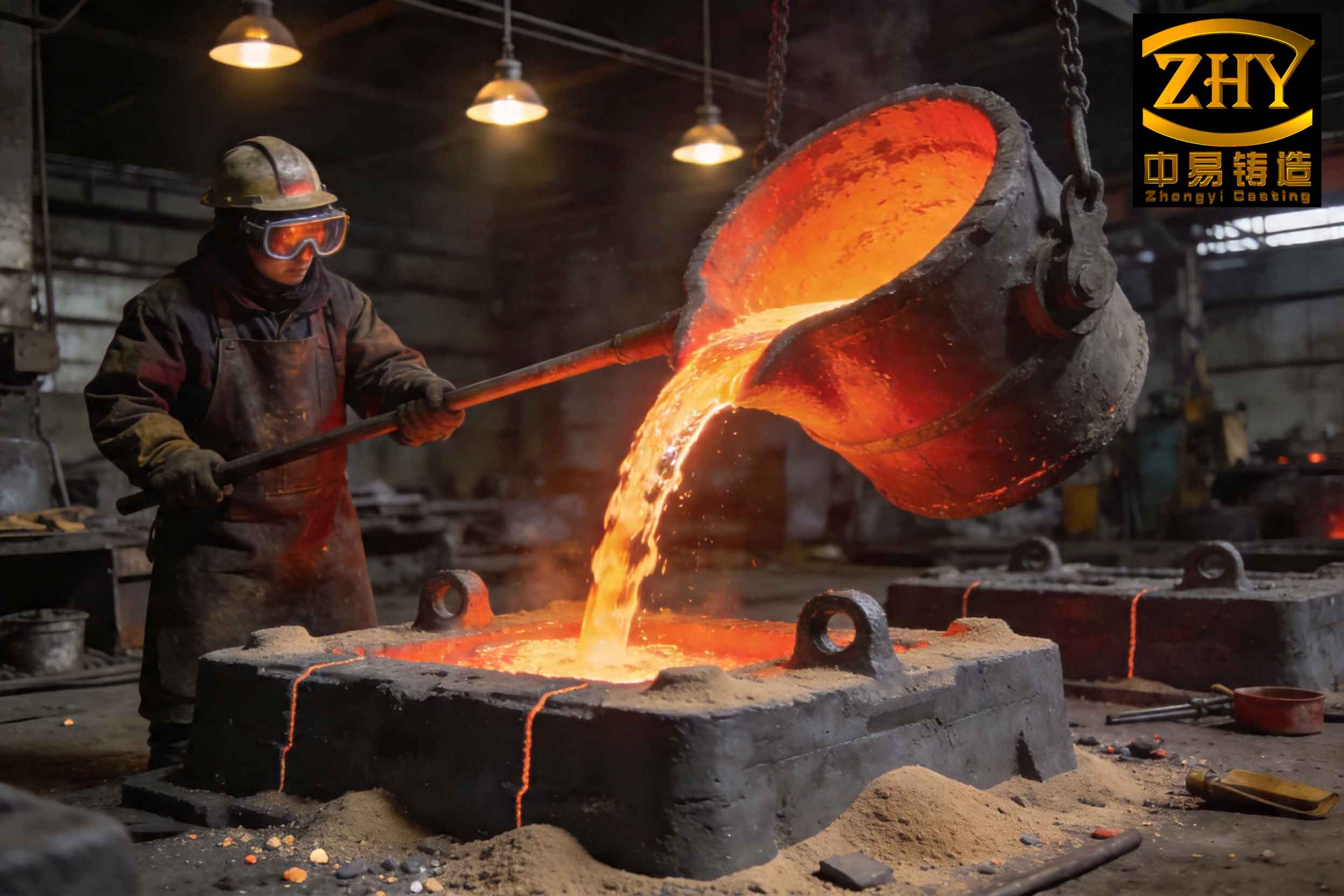
The relationship between inoculation rate, impurity load, and defect rate can be conceptualized. Assume:
$W_i$ is the weight of inoculant added (grams),
$P_{imp}$ is the impurity fraction in the inoculant (weight %),
$E_{trap}$ is the efficiency of the gating system at trapping impurities (decimal).
The mass of impurities entering the casting cavity $M_{imp}$ is approximately:
$$
M_{imp} = W_i \cdot P_{imp} \cdot (1 – E_{trap})
$$
Increasing $W_i$ directly increases $M_{imp}$, thereby raising the probability of forming slag inclusions.
A practical case study illustrates the severity. When the inoculation orifice was increased from 5 mm to 8 mm diameter to combat chill, the apparent carbide problem was solved. However, the scrap rate due to surface defects after machining soared to approximately 15%. Post-shot blasting inspection revealed severe pitting. Reverting to the original, controlled inoculation rate—while addressing the chill tendency through better charge material selection and carbon equivalent adjustment—reduced the scrap rate to below 4%. This underscores that inoculation is not a remedy for poor base iron quality but a fine-tuning tool that must be used judiciously.
Preventive measures are straightforward but require discipline:
- Use Clean, Sized Inoculant: Employ inoculant granules in the 0.5-1.0 mm range, avoiding fine powders. This reduces the impurity load per unit weight added.
- Preheat the Inoculant: Baking the inoculant at ~200-300°C removes moisture, preventing agglomeration and gas pickup.
- Optimize Gating for Slag Removal: Use non-pressurized (choke-at-bottom) gating systems with well-designed slag traps and consider finer-grade filters if the casting process allows.
- Address Root Causes of Chill: Instead of blindly increasing inoculant, adjust the melt chemistry (raise Carbon Equivalent, control Mn and Cr levels) and use charge materials with low chilling tendency.
Furnace Operational Issues: Slag Buildup and Bridging in Cupolas
Beyond treatment and inoculation, the melting operation itself can be a source of problems related to slag. A specific fault in cupola operation, distinct from general bridging or scaffold formation, involves the severe slag bonding of coke in the region just above the tuyeres (the “heart” of the coke bed).
This issue typically follows extended holding periods (“soaking”) with the blast off. Upon restarting the blast, high wind pressure is observed, with minimal gas flow at the charge door and thick smoke forcefully exiting the slag tap. Visual inspection through the tuyeres shows normal combustion at the very tip, but the intense, rising combustion zone does not establish itself higher up. The blast is effectively short-circuited, escaping through the slag tap. The cause is a dense, sintered mass of coke particles fused together by a viscous, sticky slag coating in the lower shaft.
The mechanism for this formation involves prolonged exposure of the hot coke to reducing gases and dripping, highly basic slag during the soak period. Without the scouring action of a strong, upward gas flow, the slag can coat and weld coke lumps together. The slag’s viscosity is critical; high-viscosity slags promote adhesion. Factors leading to such slags include high ash content in the coke, sand and dirt from charge materials (like rusted scrap or poorly prepared returns), and improper fluxing ratios (insufficient limestone).
The fault can be remedied without a complete shutdown. The recommended action is to operate with a very low blast rate intermittently. The low blast gently reheats the bonded mass without forcing it, gradually melting the viscous slag binder. Introducing oxygen through the tuyeres can provide localized intense heat to burn through the obstruction. Prevention is more efficient:
- Avoid excessively long soaking periods.
- Ensure charge materials are clean and free from excessive sand/soil.
- Maintain proper flux charges to ensure a fluid, low-viscosity slag that drains easily.
- Operate with a consistent, hot blast schedule to maintain stable furnace conditions.
Synergistic Control for Optimal Cast Iron Quality
The journey from molten metal to a high-performance casting is a series of deliberate, controlled interventions. Each step has the potential to either enhance properties or introduce defects. The surface hardening process demonstrates how targeted microstructural transformation can yield order-of-magnitude improvements in wear resistance and even toughness, provided the thermal cycle is precisely controlled.
Conversely, the inoculation case study is a powerful reminder that process additives must be viewed critically. Their beneficial effects (graphite refinement, carbide suppression) have an optimal window. Exceeding this window, especially with low-quality inoculant, directly trades one defect (chill) for another, more insidious one: slag inclusions. The formation of slag inclusions is not merely a cleanliness issue but a complex function of impurity load, gating efficiency, and the solidification dynamics of the specific casting process. Rapid cooling processes, while beneficial for mechanical properties, severely reduce the time available for slag floatation, making melt cleanliness paramount.
Finally, the stability of the melting operation forms the foundation. Uncontrolled events like slag-related bridging in cupolas disrupt the entire production rhythm and melt quality. A holistic view of cast iron production must therefore integrate:
- Stable, Clean Melting Practice to provide a consistent base iron.
- Precise, Minimalist Treatment and Inoculation to modify microstructure without adding impurities that lead to slag inclusions.
- Tailored Post-Casting Thermal Treatments like surface hardening to engineer specific surface properties.
- Process-Aware Gating and Mold Design that accounts for both feeding requirements and the need to trap any remaining inclusions before they can cause slag inclusions in the casting.
By understanding the underlying mechanisms—the formation of martensite, the nucleation kinetics of graphite, the fluid dynamics of slag entrapment, and the high-temperature chemistry of slags—foundry engineers can move from empirical correction to predictive control, ensuring that cast iron components meet ever-increasing demands for performance and reliability.