
In the production of critical components for energy and drainage systems, heavy-section gray iron castings present a unique set of challenges. One such component, a large bearing housing, serves as a quintessential example. The casting weighs approximately 4000 kg and is specified for a high-strength grade of gray iron, HT300, which demands superior mechanical properties. The defining structural characteristic of this component is its extreme variation in wall thickness. The main body sections feature walls of 80 mm, transitioning down to a minimum of 30 mm at certain radii. Most critically, the base plate of the housing has a massive wall thickness of 250 mm. This severe disparity creates significant difficulties during solidification, primarily manifesting as shrinkage cavities and porosity in the thickest sections, which are unacceptable defects for this application. The following details our comprehensive analysis and the step-by-step process improvement journey undertaken to solve this persistent issue, a common yet complex problem in manufacturing large gray iron castings.
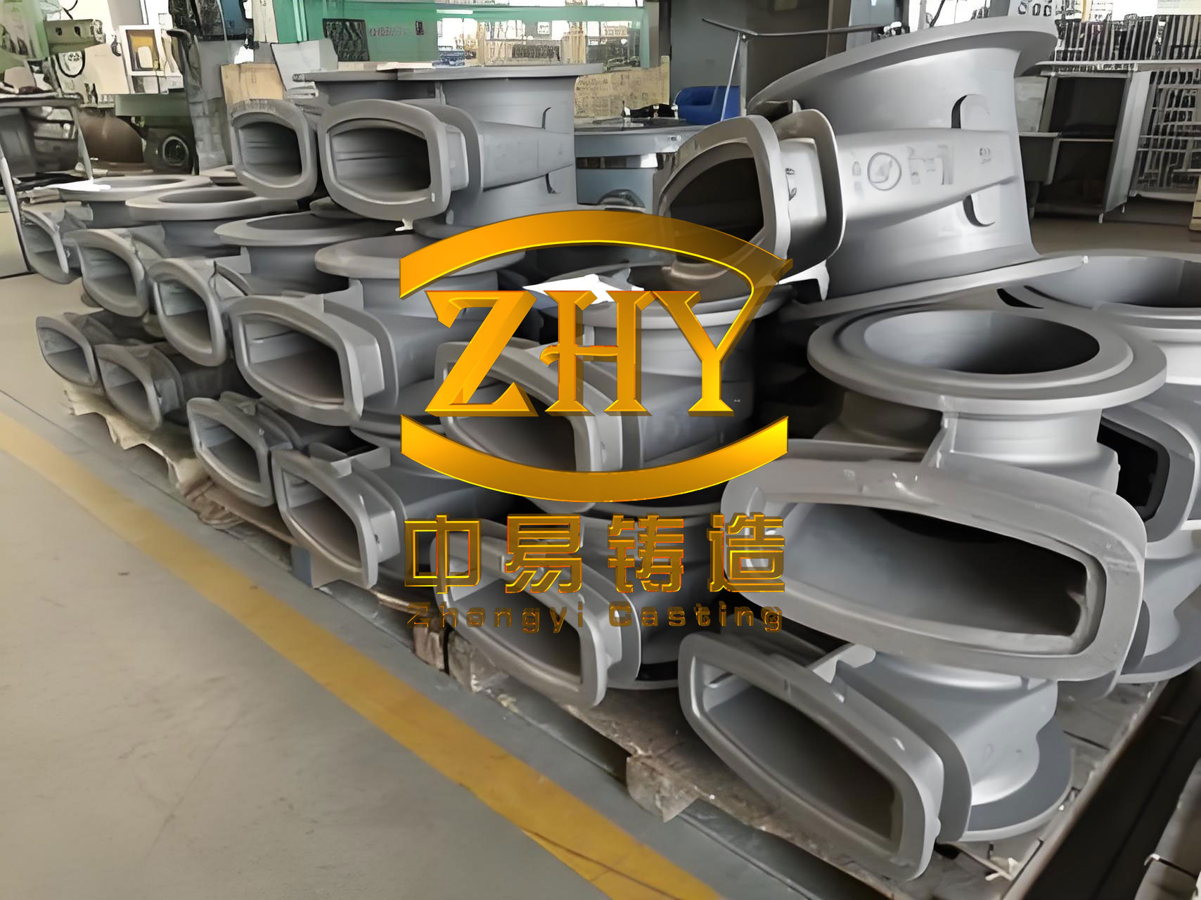
The primary challenge with such a geometry stems from the fundamental physics of casting solidification. The thin sections (30-80 mm) solidify rapidly, while the thick base section (250 mm) remains liquid for a much longer period. This disrupts a uniform cooling gradient. As the thinner walls solidify and begin to exhibit the graphite expansion characteristic of gray iron, the thick section is still in a state of liquid or mushy contraction, requiring feed metal. If this feed metal is not adequately supplied, internal voids—shrinkage cavities or macro-porosity—form. Furthermore, the prolonged cooling in the thick section can lead to the formation of coarse, type D or E graphite flakes at the surface, degrading machinability and mechanical strength, and increasing the risk of thermal stress-induced cracking at junctions between thick and thin sections.
Our initial production strategy, based on conventional wisdom for securing critical surface quality, was inherently flawed for feeding. We used a horizontally parted green sand mold. The parting line was placed at the top of the thick base plate. Consequently, the entire casting was molded in the drag (lower mold half), positioning the critical 250 mm thick base face at the bottom of the mold. The main bearing bore and its side faces were oriented vertically in the cope. A pressurized gating system was used, with a ratio of $$F_{sprue}:F_{runner}:F_{ingate} = 1 : 1.8 : 0.85$$, and gates were placed at both the upper and lower levels of the vertical side. Chills were placed against the thick base face in the drag, and several small necked-down (duckbill) risers were placed on the top surfaces (which were the thinner, 80-mm walls). The pouring temperature was maintained between 1320°C and 1340°C. The chemical composition targeted a relatively low carbon equivalent to achieve the required HT300 strength, as shown in the original parameters below.
| Parameter | Value / Specification |
|---|---|
| Material | HT300 (High-Strength Gray Iron) |
| Weight | ~4000 kg |
| Key Wall Thickness | Base: 250 mm, Body: 80 mm, Min: 30 mm |
| Primary Defect of Concern | Shrinkage Cavity in Base Section |
| Original Pouring Position | Thick Base Face Down (in Drag) |
| Original Riser Type | Duckbill Risers on Top (Thin) Sections |
| Feeding Strategy | Chills on Base, Top Risers (Ineffective Long-Distance Feed) |
The results were predictable and unacceptable. Out of six initial castings produced, four were scrapped due to major shrinkage cavities and associated shrinkage tears located directly under and around the duckbill risers on the top surface. This failure mode provided a critical insight: the risers were placed on thermally active “hot spots,” but they were too far from the actual thermal center of the casting—the 250 mm base. The long feeding distance and the intervening solidifying metal prevented effective liquid feed to the heavy section. The risers themselves, situated over thinner sections that solidified earlier, simply created localized hot spots and shrinkage at their own roots without solving the core problem. The chills on the bottom helped accelerate cooling locally but could not compensate for the lack of a direct, pressurized feed path.
A fundamental reassessment was necessary. The core principle we needed to enforce was directional solidification—creating a thermal gradient where the thickest, most feed-needy section solidifies last and is connected to a source of liquid metal until the end of its solidification. For gray iron castings, this must be balanced with the concept of “graphitic expansion feeding,” where the expansion from graphite precipitation can offset much of the shrinkage if the casting is rigidly constrained. However, for extremely heavy sections like this 250 mm base, the expansion from the outer solidified shell is often insufficient to compensate for the massive liquid/solidification contraction at the center, necessitating external feeding.
The first and most crucial decision was to flip the casting’s orientation. We moved the parting line, placing the entire casting in the cope (upper mold half). This strategic change positioned the massive 250 mm base face at the **top** of the mold. Now, the thickest section was uppermost, perfectly situated to be fed by risers placed directly upon it. The bearing bore faces were now sideways. This single change transformed the solidification dynamics, enabling a natural thermal gradient from the bottom (thin sections) to the top (thick section).
Next, we redesigned the entire feeding and gating system around this new orientation. We moved the sprue farther away from the casting (to a distance of 200 mm) to reduce its heating effect on the adjacent mold wall. The gating system remained pressurized but was recalibrated to a ratio of $$F_{sprue}:F_{runner}:F_{ingate} = 1 : 1.5 : 0.85$$, with ingates now entering from the side (bearing bore face) to ensure a smoother, less turbulent fill. Directly on the thick top face (the base), we placed large, high-conductivity chills with a thickness exceeding 120 mm. Their purpose was twofold: 1) to accelerate the initial cooling of the massive face to prevent overly coarse graphite formation, and 2) to help establish a steep thermal gradient from the chilled surface inward, promoting directional solidification towards the center of the section where a riser would feed.
The riser design required careful thought. Initially, we considered placing several large risers directly on the thick base’s top surface. However, a key lesson from the initial failure was to avoid placing a riser neck directly on the geometric and thermal “hot spot,” as this often merely transfers the shrinkage cavity to a location just below the riser. The goal is to feed the hot spot, not to be part of it. We also adjusted the metallurgical parameters. To reduce the total liquid contraction volume while maintaining mechanical properties, we slightly increased the carbon equivalent (CE) and added more copper, a pearlite promoter that increases strength without significantly increasing shrinkage tendency. We also lowered the pouring temperature range to 1300°C – 1320°C, which was now feasible because the thin sections, being filled first in the new orientation, would not be at risk of cold shuts.
| Element | Original Target (wt.%) | Revised Target (wt.%) | Purpose of Change |
|---|---|---|---|
| Carbon Equivalent (CE) | ~3.66 | ~3.85 | Increase graphitic expansion, improve castability |
| Copper (Cu) | 0.45 | 0.58 | Promote pearlite, increase strength to compensate for higher CE |
| Pouring Temperature | 1320-1340 °C | 1300-1320 °C | Reduce total liquid contraction volume |
To scientifically validate this new approach and avoid costly trial runs, we employed MAGMAsoft solidification simulation software. The initial simulation of the new layout (thick section up, with multiple top risers and chills) showed a marked improvement but revealed a lingering risk. The central risers, despite the chills, were still creating localized hot zones at their necks, indicating potential for micro-shrinkage or piping at the riser-contact junction. The simulation clearly visualized the problem: the feeding path was correct, but the riser attachment points were too thermally active.
Guided by the simulation, we implemented a final, crucial optimization: we replaced the central risers with a single, strategically placed knife-edge (or pressure) riser at one end of the thick base top. The principle of a knife-edge riser is its minimal contact area with the casting, which allows it to feed effectively but promotes rapid freezing at its neck soon after the casting has solidified, minimizing the “hot spot” effect. The remaining smaller risers on other sections had their neck dimensions reduced to accelerate their freezing as well. The revised feeding logic can be summarized by the fundamental requirement for riser efficacy:
$$ V_{riser} \cdot \rho \cdot \beta \geq V_{casting\_hotspot} \cdot \alpha $$
Where:
$V_{riser}$ is the volume of liquid metal in the riser available for feeding,
$\rho$ is the density of the liquid iron,
$\beta$ is the feeding efficiency factor (accounting for riser type and placement),
$V_{casting\_hotspot}$ is the volume of the section requiring feed,
$\alpha$ is the total volumetric shrinkage of the alloy (liquid contraction + solidification contraction).
The knife-edge riser, combined with chills, provided the necessary $V_{riser}$ with a high $\beta$ factor for the specific $V_{casting\_hotspot}$ of the base section.
The final MAGMA simulation of this optimized design confirmed a sound casting. The solidification sequence showed a clear progression from the thin bottom walls and chilled top surface, moving inwards and finally towards the single knife-edge riser. The thermal gradients were favorable, and the riser remained liquid long enough to feed the central mass of the base section before freezing off itself. No isolated liquid pockets or shrinkage indications were predicted in the finished casting body.
| Aspect | Initial Problematic Approach | Final Optimized Solution | Mechanism of Improvement |
|---|---|---|---|
| Pouring Position | Thick base down (in drag) | Thick base up (in cope) | Enables directional solidification towards risers; places feeder on thermal center. |
| Riser Design & Placement | Multiple duckbill risers on thin sections, far from thermal center. | Single knife-edge pressure riser directly on thick section edge; smaller risers with reduced necks. | Provides direct, efficient feed to hotspot; minimizes riser-contact thermal mass. |
| Auxiliary Cooling | Chills on bottom (thick section). | Heavy chills (>120mm) on top (thick section) surface. | Accelerates cooling of thick face, establishes steep thermal gradient, refines graphite. |
| Gating | Close sprue, top & bottom gating on side. | Distant sprue, side gating only. | Reduces localized superheating, ensures smooth fill from bottom-up. |
| Metallurgy | Lower CE, higher pour temp. | Higher CE with Cu addition, lower pour temp. | Balances strength and graphitic expansion; reduces liquid contraction volume. |
This optimized process was implemented in production. The initial batch of two castings was produced flawlessly. Subsequently, a production run of over thirty gray iron castings was completed with a zero scrap rate related to shrinkage. Machining of the thick base face and other critical surfaces revealed sound, dense metal with no subsurface defects. Metallographic inspection confirmed a uniform Type A graphite distribution with a fine to medium flake size (consistent with a well-fed, appropriately cooled heavy section) and a pearlite content exceeding 85%, meeting all specified mechanical properties for HT300. The hardness was consistent across the massive section.
The successful resolution of this challenging production issue provides several key learnings for the manufacture of heavy-section gray iron castings:
- Hierarchy of Design Priorities: When addressing shrinkage in castings with extreme thickness variations, establishing a favorable solidification gradient through casting orientation is paramount. This often takes precedence over the simplistic placement of critical surfaces at the bottom for cleanliness. A sound casting is a prerequisite for a clean surface.
- Strategic Feeding for Gray Iron: While gray iron’s graphitic expansion offers self-feeding properties, this mechanism has limits. For very heavy sections, judicious use of risers is essential. The choice of riser type and location is critical—it must feed the thermal center without becoming part of a larger, unsound thermal mass. The knife-edge or pressure riser is often superior for heavy gray iron castings as it provides feed while freezing quickly.
- Synergy of Complementary Techniques: No single tool solves complex solidification problems. Success is achieved through the synergistic combination of correct orientation, effective risering, aggressive chilling to control microstructure and gradient, and tailored metallurgy. The relationship can be conceptualized as an optimization function:
$$ \text{Soundness} = f(\text{Orientation}, \text{Riser}_{type,loc}, \text{Chill}_{size,loc}, \text{CE}, T_{pour}) $$
where the goal is to maximize soundness by optimizing these interdependent variables. - Role of Simulation: Numerical solidification simulation is an indispensable tool for validating and refining intuition. It allows for the rapid, cost-effective testing of multiple scenarios—like the risky central riser placement—and guides the designer toward the most robust solution before any metal is poured.
In conclusion, the production of high-integrity, heavy-section gray iron castings like this bearing housing demands a holistic and physics-based approach to process design. By systematically addressing the root cause of the defect—ineffective feeding due to poor thermal gradient management—through a combination of strategic casting reorientation, innovative riser design, controlled cooling, and compositional adjustment, we achieved a stable, zero-defect process. This case underscores that even for alloys with inherent expansion characteristics, the fundamental principles of directional solidification remain the cornerstone of quality in demanding casting applications.