
The relentless advancement of the automotive industry, particularly in passenger vehicles, has precipitated stringent demands on engine performance, technological sophistication, and component quality. The camshaft, a linchpin within the internal combustion engine, governs the precise timing and lift of valve events. Its performance directly dictates volumetric efficiency, combustion characteristics, and ultimately, fuel economy and power output. Consequently, there exists a critical industry drive to transition from traditional alloy cast irons towards materials offering a superior synergy of high strength, commendable toughness, and excellent wear resistance. This article details a first-person perspective on the successful development and production of as-cast QT750-5 synthetic ductile iron camshafts, achieved through the synergistic application of advanced scrap steel carburization techniques and sand coated iron mold casting technology. This process represents a significant leap, enabling the production of camshafts that meet the rigorous mechanical property standards (tensile strength ≥750 MPa, elongation ≥5%) directly in the as-cast condition, thereby eliminating the need for and cost of subsequent heat treatment.
1. Foundational Principles of Sand Coated Iron Mold Casting for Camshafts
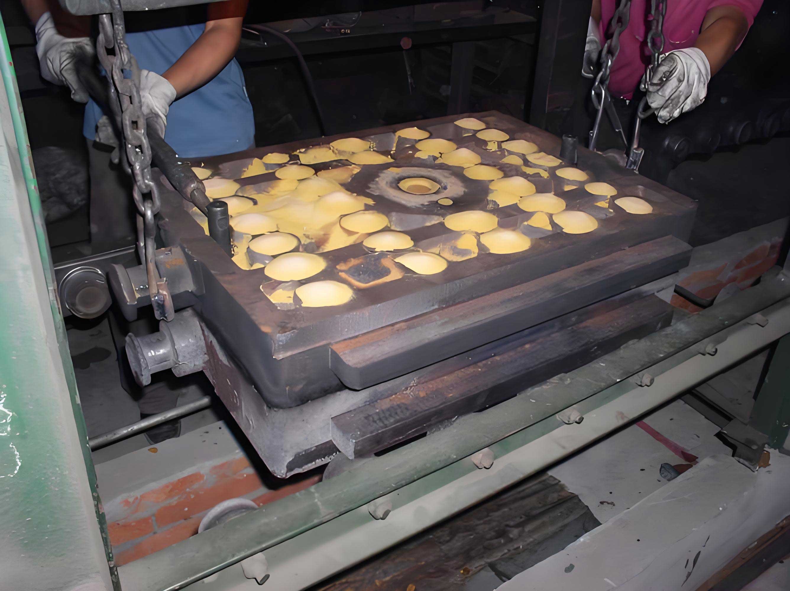
The manufacturing process hinges on the innovative sand coated iron mold casting technique. This near-net-shape process ingeniously hybridizes the characteristics of permanent mold (metal) casting and shell molding. The core principle involves a reusable iron mold (die) whose internal cavity is lined with a thin, continuous layer of resin-bonded sand, typically ranging from 4 to 10 mm in thickness.
The advantages of this method for producing high-integrity components like camshafts are multifaceted:
- Superior Cooling Rate & Refined Microstructure: The high thermal conductivity of the iron mold provides a significant chilling effect, dramatically accelerating the solidification and cooling of the molten metal. This rapid cooling suppresses the growth of graphite nodules and metallic grains, leading to a markedly refined microstructure characterized by a high nodule count, smaller graphite spheres, and finer interlamellar spacing in the pearlite. The relationship between cooling rate ( $ \dot{T} $ ) and secondary dendrite arm spacing (SDAS) or graphite nodule size ( $d_g$) is often expressed by empirical relationships such as:
$$ d_g = k \cdot \dot{T}^{-n} $$
where $k$ and $n$ are material constants. A higher $ \dot{T} $ directly results in a smaller $d_g$, enhancing mechanical properties. - Dimensional Accuracy and Surface Finish: The rigidity of the iron mold minimizes mold wall movement, ensuring exceptional dimensional precision and repeatability. The resin sand coating yields a smooth casting surface, reducing finishing operations.
- Process Consistency: The reusability of the iron mold, combined with the controlled sand layer, offers superior process stability and consistency compared to conventional green sand molding, which is vital for meeting tight automotive specifications.
The thermal dynamics of the process are crucial. The temperature of the iron mold itself becomes a critical process parameter. During continuous production cycles, the iron mold temperature ( $T_{mold}$ ) rises, reducing the effective cooling rate. This can be modeled by considering the heat flux $q$ across the sand layer:
$$ q = \frac{k_{sand}}{t_{sand}} (T_{melt} – T_{mold}) $$
where $k_{sand}$ is the thermal conductivity of the sand coating, $t_{sand}$ is its thickness, and $T_{melt}$ is the melt temperature. An increase in $T_{mold}$ decreases the driving force $(T_{melt} – T_{mold})$, lowering $q$ and $ \dot{T} $, which in turn can coarsen the microstructure. Therefore, monitoring and managing the mold temperature cycle is essential for consistent properties.
2. Charge Design, Carburization, and Chemical Composition Strategy
A foundational shift from traditional cupola melting is employed: the use of a synthetic iron base created primarily from selected steel scrap. This approach offers superior control over trace elements (particularly Ti, V, Cr, and other carbide stabilizers) and results in a cleaner iron with lower inherited impurity levels.
2.1 The Scrap Steel Carburization Process
A medium-frequency induction furnace (e.g., 500 kg capacity) is charged with a blend of clean, low-sulfur, low-phosphorus, and low-manganese steel scrap and ductile iron returns. The key to creating a hypereutectic synthetic iron lies in the controlled addition of graphitizing carburizers. High-purity carburizer with granularity between 1.0–3.0 mm, characterized by low sulfur, low nitrogen, and low ash content, is employed.
The “layered addition method” is critical for achieving high carbon recovery and uniform dissolution. A portion of the steel scrap is charged first, followed by a layer of carburizer. This sequence is repeated, building up the charge. The furnace is then powered, and the carburizer dissolves into the molten steel as it heats. The returns are added last to prevent excessive oxidation of key elements. The carbon recovery efficiency ( $ \eta_C $ ) is a vital metric:
$$ \eta_C = \frac{C_{final} – C_{initial}}{C_{added}} \times 100\% $$
where $C_{final}$ is the final carbon content, $C_{initial}$ is the carbon from the charge materials, and $C_{added}$ is the carbon mass from the carburizer. Optimizing slag conditions, temperature, and addition practice aims for $ \eta_C $ values exceeding 85-90%.
2.2 Target Chemistry and Rationale
The chemical composition is meticulously designed to achieve the target as-cast matrix of pearlite and ferrite without deleterious phases. The target range is summarized in Table 1.
| Element | Target Range | Primary Function & Rationale |
|---|---|---|
| C | 3.5 – 3.8 | Ensures graphitization, provides carbon for pearlite formation. High carbon equivalent promotes castability but must be balanced against graphite flotation risk. |
| Si | 2.2 – 2.6 | Powerful graphitizer, strengthens ferrite. Content is controlled to avoid excessive ferrite formation or embrittlement at high levels. |
| Mn | ≤ 0.35 | Moderate pearlite promoter. Kept low to minimize segregation at cell boundaries and the associated risk of intercellular carbides. |
| P | ≤ 0.06 | Strictly limited. A potent segregating element that forms brittle phosphide eutectics, severely harming toughness and machinability. |
| S | ≤ 0.05 | Strictly limited. Consumes magnesium during nodulizing, increasing Mg-Fe-Si alloy requirement and promoting dross formation. |
| Cu | 0.25 – 0.45 | Dual-function alloy: moderately promotes pearlite formation (less potent than Sn) and provides solid-solution strengthening to both ferrite and pearlitic ferrite. Also exhibits a mild graphitizing effect during eutectic solidification, helping to suppress chill (carbides). |
| Sn | ≤ 0.07 | Potent pearlite stabilizer. Even small additions (<0.1%) effectively ensure a fully pearlitic matrix. Must be carefully controlled as excess leads to embrittlement. |
The Carbon Equivalent (CE) is calculated to assess castability and graphitization potential:
$$ CE = \%C + \frac{\%Si + \%P}{3} $$
For the target range, CE typically falls between 4.3 and 4.6, placing the iron in a hypereutectic regime favorable for sand coated iron mold casting where rapid cooling can offset the inherent inoculation challenge of hypereutectic irons.
3. Melting, Nodulizing, and Inoculation Practices
Once charging and carburization are complete, the melt is superheated to 1500–1530°C and held for 5–10 minutes to ensure homogeneity and allow for slag separation. After thorough slag removal, the treatment processes commence.
3.1 Nodulizing (Spheroidization) Treatment
A rare-earth-bearing magnesium ferrosilicon alloy (e.g., Mg 5-7%, RE 0.5-2%, Si 45%, Ca 1-2%) is used as the nodulizer. The treatment is performed using the sandwich (or pocket) method in a preheated, lined transfer ladle. The alloy addition rate is 1.2–1.5% of the total iron melt weight. The reaction is vigorous, and the efficiency of magnesium recovery ( $ \eta_{Mg} $ ) is paramount:
$$ \eta_{Mg} = \frac{Mg_{absorbed}}{Mg_{added}} \times 100\% $$
Factors affecting $ \eta_{Mg} $ include treatment temperature, ladle geometry, and the presence of oxidizing elements like sulfur. Residual magnesium levels post-treatment are typically maintained between 0.03% and 0.05% to ensure stable graphite spheroidization.
3.2 Inoculation Practice
Inoculation is critical for achieving a high nodule count and preventing undercooled graphite morphologies like carbides. A calcium-barium-bearing ferrosilicon inoculant (e.g., Si 65-75%, Ca 0.5-1.5%, Ba 1-2%, Al 0.5-1.5%) is employed. A dual-inoculation strategy is adopted for maximum effectiveness:
- Ladle Inoculation: Approximately 40% of the total inoculant (0.4-0.56% of melt weight) is placed in the ladle, covering the nodulizing alloy before the iron is poured onto it.
- Stream Inoculation: The remaining 60% of the inoculant is added during the transfer of the treated iron from the treatment ladle to the pouring ladle. This “late” inoculation provides fresh nucleation sites just before solidification, counteracting fade.
The inoculant’s role is to create heterogeneous nucleation sites (e.g., (Ca,Ba)AlSi compounds, sulfides) for graphite. The nodule count per unit area ( $N_A$ ) is a direct indicator of inoculation effectiveness and is strongly influenced by the cooling rate inherent to sand coated iron mold casting.
4. Solidification Science and Microstructure Development in Sand Coated Iron Mold Casting
The unique solidification environment of the sand coated iron mold casting process fundamentally shapes the final microstructure. The rapid heat extraction leads to significant undercooling ( $ \Delta T $ ) prior to the onset of solidification.
4.1 Graphite Nucleation and Growth
The synthetic base iron, combined with effective inoculation, provides a multitude of potent nucleation substrates. The high cooling rate significantly increases the nucleation rate ( $I$ ), which can be described by classical nucleation theory:
$$ I = I_0 \exp\left(-\frac{\Delta G^*}{k_B T}\right) $$
where $ \Delta G^* $ is the critical activation energy for nucleation, $k_B$ is Boltzmann’s constant, and $T$ is temperature. The undercooling $ \Delta T $ reduces $ \Delta G^* $ for heterogeneous nucleation, thereby exponentially increasing $I$. This results in a very high nodule count, often exceeding 250-350 nodules/mm². Concurrently, the rapid diffusion of carbon through the austenite shell surrounding each graphite nodule is limited, restricting the growth rate and yielding a fine, uniform graphite sphere size distribution, typically corresponding to ASTM size 6-7 (diameter ~15-30 μm).
4.2 Matrix Formation: Pearlite vs. Ferrite
The as-cast matrix is a mixture of pearlite and ferrite (“bull’s-eye” ferrite surrounding graphite nodules). The final ratio is controlled by a combination of chemistry and cooling rate.
- Alloying (Cu, Sn, Mn): These elements segregate to the austenite during solidification and lower the austenite-to-ferrite transformation temperature ( $A_{e3}$ ) on the continuous cooling transformation (CCT) diagram. They shift the “nose” of the transformation curve to longer times, making the diffusion-controlled ferrite formation less likely compared to the shear-dominated pearlite transformation under the given cooling conditions. The potency follows Sn > Cu > Mn.
- Cooling Rate: The rapid cooling imposed by the sand coated iron mold casting process pushes the solid-state transformation towards higher undercooling, favoring the formation of fine pearlite. The interlamellar spacing of pearlite ( $S_0$ ) is inversely related to the undercooling below the eutectoid temperature ( $ \Delta T_e $ ):
$$ S_0 \propto \frac{1}{\Delta T_e} $$
Faster cooling increases $ \Delta T_e $, leading to a finer $S_0$, which significantly enhances strength. - Silicon and Carbon Equivalent: High Si and CE promote the formation of ferrite. Therefore, their levels are balanced against the pearlite-promoting alloys to achieve the target 5-35% ferrite content necessary for achieving ≥5% elongation.
The absence of free carbides and phosphide eutectics is a testament to the well-balanced chemistry (low Mn, controlled Cu, low P) and the inherent graphite-favoring solidification conditions provided by the synthetic iron and the mold’s thermal characteristics.
5. Mechanical Performance and Microstructural Correlation
The culmination of the process—charge design, carburization, alloying, treatment, and sand coated iron mold casting—is validated through mechanical testing and metallographic analysis. Table 2 presents data from experimental casts, illustrating the relationship between process variables, microstructure, and mechanical properties.
| Sample ID | Charge Mix (Scrap/Returns) | Tensile Strength (MPa) | Elongation (%) | Estimated Ferrite (%) | Estimated Pearlite (%) | Nodularity Grade | Graphite Size Grade |
|---|---|---|---|---|---|---|---|
| 01-03 | 50/50 | 750 – 780 | 7.2 – 7.8 | 25 – 35 | 65 – 75 | II | 6-7 |
| 04-06 | 80/20 | 805 – 825 | 5.1 – 5.8 | 5 – 10 | 90 – 95 | II-I | 7-6 |
The analysis of the data reveals key insights:
- Effect of Scrap Ratio: Increasing the scrap steel percentage from 50% to 80% (Samples 04-06) enhances the nodularity grade and refines the graphite size. This is attributed to the cleaner metallic base with fewer inherited impurities that can interfere with graphite spheroidization, coupled with the increased number of heterogeneous nuclei from the carburization process. This refinement contributes to the higher tensile strength observed.
- Microstructure-Property Relationship: The primary determinant of the tensile strength is the volume fraction of pearlite. A linear rule-of-mixtures model provides a first approximation:
$$ \sigma_{UTS} \approx V_f^{\alpha} \sigma^{\alpha} + V_f^{P} \sigma^{P} $$
where $V_f$ is volume fraction and $\sigma$ is the strength of the respective phase (ferrite $\alpha$, pearlite P). Pearlite, especially with a fine interlamellar spacing, has a significantly higher $\sigma^{P}$ than ferrite. Therefore, samples 04-06 with 90-95% pearlite exhibit UTS > 800 MPa. Elongation is primarily governed by the ferrite content, which provides ductility. Samples 01-03 with 25-35% ferrite achieve elongation >7%, comfortably exceeding the 5% minimum. - Role of Mold Temperature: As the iron mold temperature increases during prolonged casting cycles, the effective cooling rate decreases. This can lead to a slight coarsening of graphite, a reduction in nodule count, and an increase in the pearlite lamellar spacing, all of which can cause a slight degradation in mechanical properties (lower UTS, potentially higher elongation). This underscores the need for thermal management in the sand coated iron mold casting process.
- Synthesis of Effects: The final mechanical properties are a complex outcome of multiple interactive factors summarized by the following functional relationship:
$$ \text{Properties} = f(\text{Scrap Ratio}, \, T_{mold}, \, [\text{Alloys}], \, CE, \, \text{Treatment Efficacy}) $$
The sand coated iron mold casting process is the enabling platform that provides the necessary high cooling rate to capitalize on the refined nucleation potential of the synthetic iron.
6. Conclusion and Industrial Implications
The successful production of as-cast QT750-5 synthetic ductile iron camshafts demonstrates a viable and technologically advanced manufacturing route. The integration of scrap steel carburization with sand coated iron mold casting technology provides a compelling solution for high-volume production of high-performance cast components.
The key achievements and understandings are summarized as follows:
- The sand coated iron mold casting process is instrumental in generating the rapid solidification and cooling conditions required to refine the graphite structure (high nodule count, size 6-7) and the metallic matrix (fine pearlite interlamellar spacing).
- A synthetic iron base derived from selected steel scrap and graphitizing carburizers offers superior control over trace elements and provides an ideal foundation for achieving high-quality ductile iron.
- The mechanical properties (UTS ≥750 MPa, El. ≥5%) are directly attainable in the as-cast state by precisely balancing the chemical composition—particularly the carbon equivalent and the levels of pearlite-promoting (Cu, Sn) and ferrite-promoting (Si) elements—within the constrained cooling environment of the process.
- The microstructure is characterized by well-formed, finely distributed graphite nodules in a matrix of fine pearlite with a controlled amount of bull’s-eye ferrite (5-35%), essentially free of detrimental carbides and phosphides.
- Process parameters such as the scrap-to-returns ratio, iron mold temperature, and alloy addition levels are critical control variables that must be optimized and maintained to ensure consistent mechanical properties batch after batch.
This technological approach represents a significant advancement over traditional alloy cast iron camshafts, offering a superior combination of strength, durability, and weight-saving potential for modern, high-efficiency engines. The sand coated iron mold casting process, coupled with synthetic iron metallurgy, stands as a robust and scalable manufacturing platform for the future of high-integrity automotive castings.