
the structure and technical requirements of the V-type gas engine cylinder block casting, analyzes the production difficulties of the casting, and decides to adopt the 3D printing sand core technology. The sand cores on both sides form the exterior structure of the casting side face and the riser, the middle integral sand core forms the internal cavity and the two end faces structures, and the two sand cores at the bottom form the top exterior structure of the cylinder holes and the gating system. The sand cores are positioned through the concave and convex positioning bosses. The production results show that the casting dimensional accuracy can reach CT9 grade, the maximum RT in the critical area of the casting is grade I, there is no leakage after 30 minutes of 1 MPa water pressure test, all inspections are qualified, the metallurgical structure and mechanical properties also meet the technical requirements. The use of 3D printing technology improves the production efficiency, enhances the product quality, and reduces the production difficulty.
With the increasingly fierce market competition, the quality requirements for engine products are getting higher and higher, especially for high-quality and fast delivery. Traditional casting has been difficult to meet the requirements of high-quality and fast delivery when facing high-demand products such as cylinder blocks. The cylinder block casting studied in this paper is a core component of the gas engine, with an overall appearance and internal cavity in a “V” shape, composed of cylinder ports, water cavities, camshaft cavities, etc. As the backbone structure of the engine, this casting has very high quality requirements. Through the innovative research on the 3D printing process of the gas engine cylinder block product, the author has successfully developed an efficient and stable 3D printing process method for the cylinder block casting.
1. Casting Structure and Technical Requirements
1.1 Casting Structure
The external dimensions of the casting are 1,700 mm by 1,000 mm by 900 mm, the single weight of the casting is 2,130 kg, and the main wall thickness is 8 mm.
1.2 Quality Requirements
The casting material is gray iron, which is implemented in accordance with the standard of ASTM A247 – 2016 “Standard Test Method for Evaluating the Microstructure of Graphite in Cast Iron”. The graphite is of type A, with a size of 4 – 5 grades, the volume fraction of pearlite in the matrix structure is ≥ 90%, the tensile strength of the body is ≥ 258 MPa, and the hardness is 170 – 241 HB. The RT detection level is grade II in the critical area, and there is no leakage after 30 minutes of 1 MPa water pressure test.
2. Process Scheme
2.1 Difficulty Analysis
The cylinder block casting has a complex structure with many internal cavities. For such structural castings, the traditional casting process method needs to consider the following points:
(1) The water cavity of this cylinder block is a relatively independent structure, and the sand core for fixing the water cavity is required to ensure the wall thickness of the casting. In traditional casting, it is generally produced by forming separately and then marking it with the outer mold or the main core. This production method has a large deviation in the size of the sand core. Due to the long and thin sand core in separate forming, it is easy to deform, and the production efficiency is very low.
(2) The V-type cylinder block belongs to the 12-cylinder series, with 6 inner gears and 6 camshaft cavities. In traditional casting, each inner gear and camshaft cavity must be formed with a sand core. This method also brings size problems, sand inclusion and other quality risks, and the operation efficiency is low.
2.2 3D Printing Process
2.2.1 Design of 3D Printing Sand Core Core Segmentation Scheme
For the 3D printing process, the influence of the casting structure on it is relatively less limited than that of the traditional process, and there are more options for the scheme. A good core segmentation scheme has a great impact on the casting quality and the on-site operation. Considering the structure of such cylinder block products, through comprehensive considerations such as simple operation, fewer sand cores, and easy control of product quality.
According to this core segmentation scheme, the casting can be formed only with 5 sand cores, and the 5 sand cores are used to form the overall structure of the casting, and the bottom sand core is convenient for placing the gating system.
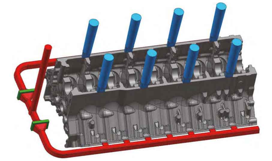
2.2.2 Design of Gating and Riser System
From the perspective of the structure of the entire cylinder block casting, the wall thickness of most positions of the casting is less than 15 mm, and these thin-walled cavity structures are not conducive to the design of the internal gate position, which is easy to cause sand washing defects. The relatively thick position of the casting is between the cylinder ports, where the wall thickness is 60 mm, and the inflow of the internal gate at this position can avoid the risk of sand inclusion caused by the direct impact on the sand core. In order to ensure that the gating system can better play the role of slag removal, so that the first cold molten iron and dirty molten iron do not enter the mold cavity and reduce the flow rate of the molten iron, the runner of the gating system is arranged below the casting, and an open gating system with a filter screen is adopted. The cross-sectional area ratio of the gating system is ΣF_vertical: ΣF_horizontal: ΣF_internal = 1: (1.5 – 2): (1.5 – 2). The filter screen uses a SiC filter screen with a size of 100 mm by 100 mm by 25 mm, and the pouring temperature is 1,350 °C.
In order to ensure the feeding of the casting and the uniformity of the temperature field, a special anti-sand-dropping side riser for the foot is designed, and an air outlet riser is also designed at the bearing seat position for the air outlet of the mold cavity.
2.2.3 Simulation Analysis of the Inflow of the Gating System
In order to ensure the smooth filling of the molten iron, the low flow rate, and the stable rise of the liquid level during the inflow of the molten iron, and to prevent sand washing, turbulent flow of the molten iron, and other problems, the designed gating system is simulated and analyzed, and the simulation results. It can be seen that the flow rate of the internal gate is very low, only 0.5 m/s, when the molten iron enters the mold cavity, and the filling process of the entire casting is very stable, which meets the requirements of the process design.
(a) 40% Mold Filling
(b) 80% Mold Filling
(c) 100% Mold Filling
2.2.4 Design of 3D Printing Sand Core
The casting only needs 5 sand cores to meet the requirements. The sand cores on both sides form the side appearance structure and the riser of the casting, the middle integral sand core forms the internal cavity and the two end faces structures, and the bottom 2 sand cores form the cylinder port appearance structure and the gating system. The sand cores are positioned through the concave and convex positioning bosses, which ensures the accuracy and efficiency of the core setting.
3.Comparison between 3D Printing and Traditional Process
By using the 3D printing process for one-time forming and design of the inner cavity core, compared with the traditional slicing process, it has the following advantages:
(1) Simple process and shortened production cycle. The entire process only requires 5 sand cores, while the traditional slicing requires a series of processes and tooling designs such as molds, core boxes, core irons, and sand boxes, eliminating the mold making cycle of the traditional casting method. Table 1 shows the comparison of the production cycles of the two casting methods.
Table 1 Production Cycle Comparison of Two Casting Methods
| Production Order | Production Cycle (Days) |
|---|---|
| 3D Printing | 1 |
| Traditional Mold Production | 1 |
| Mold Making | 30 – 60 |
| Sand Core / Sand Core Making | 1 |
| Mold Closing | 2 |
| Pouring | 1 |
(2) Economic comparison. Since the 3D printing product does not require mold making, its production cost is slightly higher than that of traditional casting. Taking this cylinder block casting as an example, compared with traditional wood mold production, the 3D printing is more economical than the traditional wood mold when the production quantity is within 100 pieces.
(3) Sand core strength: The resin used in 3D printing is different from that in the traditional process, the curing agent can be the same as that in traditional casting, and the raw sand is the same as that required in traditional casting. The final average compressive strength can reach 6 – 7 MPa.
4. Production Results
Using the above process design scheme, the cylinder block casting was produced, and the size, NDT, and leakage tests were carried out according to the standards required by the customer. The test results show that the final dimensional accuracy of the casting can reach CT9 grade, the maximum RT in the critical area of the casting is grade I, there is no leakage after 30 minutes of 1 MPa water pressure test, all tests are qualified, and the metallurgical structure and mechanical properties also meet the technical requirements.
5. Conclusion
Practice has proved that the V-type gas engine cylinder block casting produced using the 3D printing sand core technology improves the production efficiency, enhances the product quality, and reduces the production difficulty, which can meet the batch and efficient production of such cylinder block castings.