
This study details the manufacturing process for a gray iron frame shell casting with dimensions 1,300 mm × 800 mm × 750 mm and mass of 360 kg. Key technical requirements include a 3 mm clearance between internal attachments and non-machined surfaces, 1 mm flatness tolerance for the internal bottom plane, and defect-free machined surfaces. The shell casting exhibits variable wall thicknesses (8 mm primary walls, 30 mm thick sections), creating challenges in dimensional stability due to differential contraction.
Mold Structure Design
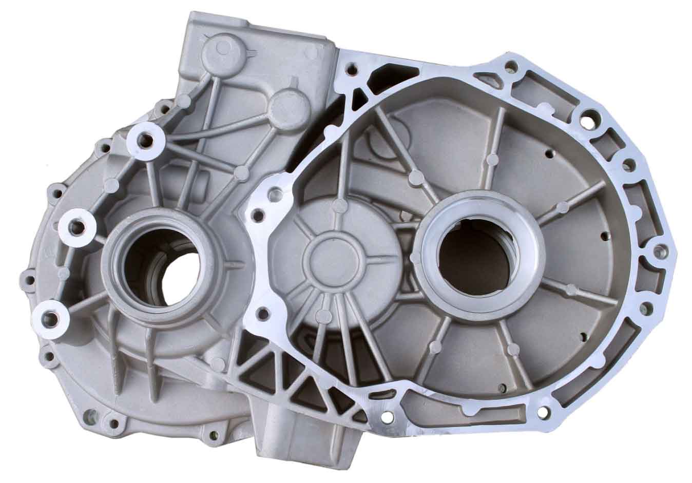
Furan resin sand was selected for manual molding and core-making. Cast iron patterns ensured high strength and wear resistance, while aluminum core boxes facilitated operational efficiency. Horizontal parting was implemented along the shell casting’s upper plane (Figure 1), incorporating loose pieces in undercut regions. The main body core utilized a monolithic design with hollow sections to enhance collapsibility, maintaining a minimum sand thickness of 100 mm. A slide-and-guide mechanism enabled efficient core box operation, critical for dimensional consistency in complex shell castings.
Casting Process Design
Differential Contraction and Reverse Deformation
Contraction allowances were directionally applied to accommodate the shell casting’s geometry:
- Longitudinal (free contraction): 0.8%
- Transverse/height (restricted contraction): 0.4%
Reverse deformation was engineered to counteract warpage on the critical bottom plane. A convex profile with 1 mm maximum elevation at the center, tapering to zero at edges (Figure 4), was calculated using the warpage compensation formula:
$$ \delta_r = k \cdot L^2 \cdot \Delta T \cdot \alpha $$
Where \(\delta_r\) = reverse deformation (mm), \(k\) = restraint coefficient (0.4 for this shell geometry), \(L\) = characteristic length (mm), \(\Delta T\) = temperature gradient (°C), and \(\alpha\) = thermal expansion coefficient (10.4×10⁻⁶/°C for HT250).
Dimensional Stabilization with Process Ribs
Transverse and longitudinal process ribs were integrated to synchronize cooling contraction (Figure 3). Rib dimensions followed empirical relationships relative to shell casting wall thickness (\(t\)):
$$ W_r = 1.5t \quad \text{and} \quad H_r = 2t $$
Gating System Optimization
A top-poured ceramic tube system prevented gas entrapment in upper sections. A semi-choked design with area ratios \(\Sigma F_{\text{sprue}} : \Sigma F_{\text{runner}} : \Sigma F_{\text{ingate}} = 1.2 : 1.5 : 1\) enhanced slag capture. Pouring time (\(T_p\)) was calculated based on mass (\(W\)) and section modulus:
$$ T_p = k \sqrt{W} $$
Where \(k\) = 1.8–2.2 seconds/kg⁰·⁵ for shell castings. One riser and multiple vent pins were strategically placed.
| Component | Cross-section (cm²) | Flow Rate (kg/s) | Function |
|---|---|---|---|
| Sprue | 28.3 | 12.5 | Pressure control |
| Runner | 35.0 | 10.0 | Slag separation |
| Ingates | 23.3 | 15.0 | Flow distribution |
Molding, Core-Making, and Assembly
Cores were reinforced with steel inserts for handling integrity. Coating application parameters:
- Coating thickness: 0.3–0.5 mm
- Alcohol-based carrier
- Ignition drying
Core position was verified using custom gauges before closing. The high sand-to-metal ratio (3.5:1) necessitated rigorous venting to prevent gas-related defects in the shell casting.
Melting and Pouring
A 1-ton induction furnace melted charge materials: Q12 pig iron, 8 mm steel scrap, and returns. Key process controls:
| Element | Target | Range | Effect on Shell Casting |
|---|---|---|---|
| C | 3.40 | 3.35–3.45 | Fluidity, shrinkage |
| Si | 1.60 | 1.55–1.65 | Matrix control |
| Mn | 0.80 | 0.75–0.85 | Pearlite stabilization |
| Cr | 0.20 | 0.18–0.22 | Hardness control |
| S | 0.10 | ≤0.12 | Inoculation response |
High-barium ferrosilicon (0.4% of tap weight) was used for inoculation. Pouring parameters:
- Temperature: 1,400–1,420°C
- Pouring basin: Maintained full
- Duration: 25–30 seconds
Thermal management during solidification followed the Chvorinov equation modified for shell geometries:
$$ t_s = B \left( \frac{V}{A} \right)^n $$
Where \(t_s\) = solidification time (min), \(B\) = mold constant, \(V\) = volume (cm³), \(A\) = surface area (cm²), and \(n\) = exponent (1.5–2.0 for shell castings).
Production Validation
Initial trials confirmed dimensional compliance with technical specifications. Reverse deformation effectively neutralized differential contraction in all five test shell castings. Subsequent production of 150 units demonstrated consistent quality:
- Dimensional accuracy: IT9 achieved in 98% of features
- Flatness: 0.8–1.0 mm across batch
- Defect rate: <0.5% on machined surfaces
Process capability indices (\(C_{pk}\)) for critical dimensions exceeded 1.33, confirming robust manufacturing for this shell casting.
Conclusions
Reverse deformation design is essential for dimensional accuracy in frame-type shell castings. Process ribs significantly improve geometric consistency by synchronizing contraction forces. The integrated approach combining directional contraction allowances, thermal management, and optimized gating delivers reliable production of complex shell castings. These principles are transferable to similar thin-wall geometries where differential contraction induces warpage.