
I began this study because I needed a faster and more economical way to develop gas turbine blades without committing to a long and expensive sequence of die trials. In my experience, a conventional investment casting route usually follows a fixed chain: I prepare an initial process, I make a metal die, I inject wax patterns, I assemble a tree, I build a ceramic shell, I dewax, I fire the shell, I pour metal, and I inspect the casting. If the inspection fails, I must revise the die and repeat much of the sequence. In my project, that cycle often took one to three months before I could lock the tooling. For a gas turbine blade with a complex airfoil, a hollow internal passage, and a demanding root geometry, this delay is not only costly but also technically risky. I therefore turned to a rapid investment casting route in which I printed the blade pattern in ABS, attached it to a conventional wax gating system, built a ceramic shell, removed the pattern, fired the shell, and poured metal. I also considered how the same thermal-stress logic can appear in evaporative pattern casting, because both rapid investment casting and evaporative pattern casting rely on an expendable pattern that must disappear before or during filling. Although my main process was rapid investment casting, I kept evaporative pattern casting in mind as a related family of expendable-pattern methods.
My objective was not merely to demonstrate that a 3D printed pattern could be cast. I wanted to understand why my first shells cracked, why the resulting blades showed flash and dimensional drift, and how I could optimize the blade geometry and shell process so that I obtained a sound gas turbine blade. I used a combination of process trials, deformation coordination equations, and finite element analysis. In my first trials, I used five slurry and sand layers. The shells cracked during burnout and handling, especially near the leading and trailing edges. I repaired the shells manually and still poured stainless steel, but the castings had surface defects and unacceptable dimensional variation. I then modeled the ABS pattern and the ceramic shell as a simplified concentric cylinder system, derived the compatibility condition between their thermal expansions, and used finite element software to calculate the equivalent stress distribution. The results showed that the maximum stress occurred at the airfoil edges where the curvature was highest. I then optimized the blade edge radii, changed the internal structure of the printed ABS pattern to a lower-density lattice, and increased the shell build from five layers to six and a half layers. The revised trial produced a complete shell and a high-quality blade casting. Throughout this work, I repeatedly compared my observations with evaporative pattern casting, because the same need to manage pattern expansion, shell constraint, and thermal gradients is central to evaporative pattern casting as well.
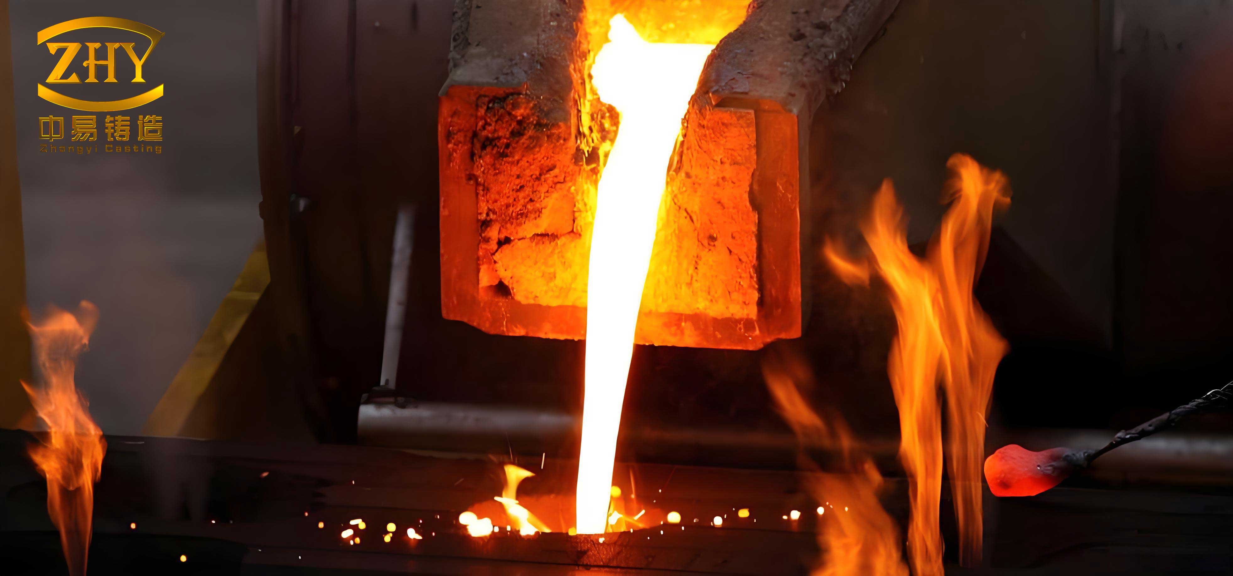
In my initial process route, I first created a three-dimensional digital model of a gas turbine compressor moving blade. I converted the model to STL format and printed it in ABS using fused deposition modeling. I chose ABS because it could be printed with adequate dimensional fidelity, it could be bonded to wax gating, and it could be thermally removed from the shell. I then attached the printed ABS blade to a wax runner and gating system. I selected the root as the metal entry region because the root has a large cross section and can feed the airfoil without introducing a thin, high-velocity jet directly into the thin trailing edge. This gating choice was important: a poor gate location can increase local shell stress and can also create turbulence that damages the shell in evaporative pattern casting or in rapid investment casting. I then built the ceramic shell around the assembled pattern tree. In the first trial, I applied five layers of slurry and stucco. I controlled the slurry density and viscosity for each layer, and I dried the tree in a controlled temperature and humidity room after every coating. The first layer was a fine refractory coating, and the later layers provided strength and thermal shock resistance. I inserted the image below at this stage because it illustrates the general full-mold and expendable-pattern casting context that I used as a reference while planning my shell and pattern removal strategy.
After the shell was dry, I removed the wax gating and the ABS blade pattern. The wax was removed by a standard dewaxing operation, and the ABS pattern was burned out during firing. I then fired the shell in the range of 970 to 1030 °C. This firing step was critical. If the firing temperature was too low, the shell did not develop sufficient strength, and it cracked under the thermal stress of metal pouring. If the firing temperature was too high, the shell deformed and the blade dimensions drifted. I observed both types of failure in my early trials, which convinced me that the firing schedule had to be tied directly to the shell thickness, the pattern material, and the blade curvature. I also recognized that the same window exists in evaporative pattern casting: the pattern must decompose or vaporize in a controlled way, and the surrounding refractory must have enough permeability and strength to survive the event. In my case, the shell cracked mainly near the leading and trailing edges, which are the regions with the smallest radii of curvature and the highest constraint.
My first castings confirmed that the process was feasible but not yet robust. I obtained a metal blade, but the shell had cracks, the blade surface had flash and rough patches, and the airfoil dimensions were inconsistent. I therefore divided the problem into three parts: the thermal expansion mismatch between the ABS pattern and the ceramic shell, the stress concentration caused by the airfoil edge geometry, and the shell thickness and firing schedule. I also reviewed the differences between conventional investment casting and my rapid route. The table below summarizes the comparison I used in my planning. I included evaporative pattern casting in the comparison because it is another expendable-pattern process in which pattern removal and refractory integrity dominate the final result.
Table 1. Comparison of process routes that I considered for the blade development.
| Process route | Pattern material | Tooling need | Typical lead time in my assessment | Main shell or refractory risk |
|---|---|---|---|---|
| Conventional investment casting | Wax | Metal die required | Long, often one to three months for iteration | Wax expansion, shell cracking during dewax and firing |
| Rapid investment casting with printed ABS | ABS printed by FDM | No metal die for the pattern | Short, days to a few weeks per iteration | ABS expansion, burnout residue, shell cracking |
| Evaporative pattern casting | Expendable foam or vaporizable pattern | Pattern tooling may still be needed | Moderate to short depending on pattern production | Pattern decomposition, coating or sand collapse, gas defects |
| Hybrid rapid investment casting | Printed pattern plus wax gating | No blade die, but gating fixture needed | Short | Thermal mismatch, edge stress concentration, shell thickness |
To analyze the shell cracking, I simplified the blade pattern and shell as two concentric cylinders. This is not a complete representation of a blade, but it captures the essential thermal expansion conflict. I assumed that the ABS pattern was an infinite cylindrical ring with inner radius \(a\) and outer radius \(b\), and that the ceramic shell was a surrounding cylinder with thickness \(x\). I assumed perfect bonding at the interface. When the temperature rises from \(t_1\) to \(t_2\), the temperature change is \(\Delta t = t_2 – t_1\). Both materials expand, but the ABS pattern has a much larger coefficient of thermal expansion than the ceramic shell. The shell therefore constrains the pattern, and the pattern pushes outward on the shell. The pattern undergoes an inward elastic compression, while the shell undergoes an outward elastic expansion. I wrote the circumferential deformation of the pattern as
$$X_1 = 2\pi b \alpha_1 \Delta t – \frac{2\pi b \sigma_1}{E_1}$$
and the circumferential deformation of the shell as
$$X_2 = 2\pi b \alpha_2 \Delta t + \frac{2\pi b \sigma_2}{E_2}$$
where \(\alpha_1\) and \(\alpha_2\) are the thermal expansion coefficients of the ABS pattern and the shell, \(E_1\) and \(E_2\) are their elastic moduli, and \(\sigma_1\) and \(\sigma_2\) are the hoop stresses in the pattern and shell. Because the two bodies remain in contact, their circumferential deformations must be equal:
$$X_1 = X_2$$
Substituting the expressions for \(X_1\) and \(X_2\) gives the deformation coordination equation:
$$\alpha_1 \Delta t – \frac{\sigma_1}{E_1} = \alpha_2 \Delta t + \frac{\sigma_2}{E_2}$$
I then related the hoop stresses to the contact pressure \(p\) at the interface. For a thin ring, I used the approximations
$$\sigma_1 = \frac{p b}{t_1}$$
and
$$\sigma_2 = \frac{p b}{t_2}$$
where \(t_1\) is the effective thickness of the ABS pattern wall and \(t_2\) is the shell thickness. Combining these relations with the compatibility equation gives the interface pressure:
$$p = \frac{(\alpha_1 – \alpha_2)\Delta t}{b\left(\frac{1}{E_1 t_1} + \frac{1}{E_2 t_2}\right)}$$
The shell hoop stress is therefore
$$\sigma_2 = \frac{(\alpha_1 – \alpha_2)\Delta t}{t_2\left(\frac{1}{E_1 t_1} + \frac{1}{E_2 t_2}\right)}$$
This equation shows the key trends I observed. The shell stress increases when the thermal expansion mismatch \(\alpha_1 – \alpha_2\) is large, when the temperature rise is large, and when the shell is thin. It decreases when the shell thickness \(t_2\) increases and when the ABS pattern is made more compliant, which means a lower effective modulus or a lower-density internal structure. I also recognized that the same trends apply in evaporative pattern casting when a rigid refractory coating or shell constrains a vaporizing or expanding pattern. Even though evaporative pattern casting often uses loose sand rather than a fully bonded ceramic shell, the local coating and the surrounding mold can still impose constraint, and the same compatibility logic can be adapted.
For a more detailed stress estimate, I also considered the thick-cylinder hoop stress formula. At a radial position \(r\) in the shell, the hoop stress under internal pressure \(p\) can be written as
$$\sigma_{\theta} = \frac{p r_i^2}{r_o^2 – r_i^2}\left(1 + \frac{r_o^2}{r^2}\right)$$
where \(r_i\) is the inner radius and \(r_o\) is the outer radius of the shell. This formula indicates that the hoop stress is highest at the inner surface and decreases outward. It also explains why an increase in shell thickness reduces the stress level, although the benefit diminishes as the thickness becomes very large. I also used a simple thermal stress expression for a constrained body:
$$\sigma_{th} = \frac{E \alpha \Delta T}{1 – \nu}$$
where \(\nu\) is Poisson’s ratio. This expression is not a full solution for the blade shell, but it helped me rank the material and geometry effects. In my case, the ABS pattern had a much higher thermal expansion coefficient than the ceramic shell, so the shell was placed in tension as the assembly heated. The thin airfoil edges could not tolerate that tension, especially when the edge radius was small. This interpretation was consistent with the crack locations I observed. It also matched my reading of evaporative pattern casting literature, where pattern expansion and coating strength are often balanced to avoid coating cracks and gas defects.
I then built a two-dimensional finite element model of the blade cross section and the surrounding shell. I used a parameterized modeling system to create both solid and hollow blade sections. I also created shell thicknesses of 6 mm and 8 mm. I imported the two-dimensional geometry into finite element software and used a bonded contact condition between the ABS pattern and the shell. I selected a four-node plane element, PLANE13, which can handle thermal and structural fields. I meshed the model with a refined mesh near the leading and trailing edges because those regions have high curvature and high stress gradients. I assumed that the assembly was heated from room temperature, 22 °C, to 200 °C. I represented the heating history with a linear function:
$$K = 22 + a t$$
where \(K\) is the temperature in degrees Celsius at time \(t\), and \(a\) is a constant heating rate. I performed a static thermal stress analysis at 150 °C. The material properties I used are listed in Table 2. These values were chosen to represent the compliant ABS pattern and the stiffer ceramic shell in my trial. I then calculated the equivalent stress distribution and compared the maximum values for different shell thicknesses and pattern internal structures.
Table 2. Material properties used in my finite element analysis.
| Material | Elastic modulus | Poisson’s ratio | Thermal expansion coefficient |
|---|---|---|---|
| ABS printed pattern | 1.0 MPa | 0.43 | 92.0 × 10⁻⁶ /°C |
| Ceramic shell | 630 MPa | 0.26 | 4.0 × 10⁻⁶ /°C |
The finite element results showed that the maximum equivalent stress was concentrated at the leading and trailing edges of the airfoil. These are the locations where the radius of curvature is smallest and where the shell must conform to a sharp change in geometry. In my first trials, these were exactly the locations where the shell cracked. The stress cloud also showed that the stress decreased toward the mid-chord region, where the airfoil surface is relatively flat. I summarized the maximum equivalent stress values in Table 3. The values are comparative rather than absolute, because the real blade has a three-dimensional geometry and a transient temperature field, but they were useful for ranking the design changes. I also noted that the same edge-driven stress concentration can occur in evaporative pattern casting when a thin coating is applied to a sharp foam edge. In evaporative pattern casting, the coating must survive pattern decomposition and metal filling, so edge radius and coating thickness are just as important as they are in my rapid investment casting route.
Table 3. Maximum equivalent stress in my finite element cases.
| Case | Shell thickness | Pattern internal structure | Maximum equivalent stress | Observed or predicted crack risk |
|---|---|---|---|---|
| A | 6 mm | Solid ABS | 18.7 MPa | Very high at leading and trailing edges |
| B | 6 mm | Lattice ABS | 12.4 MPa | Moderate |
| C | 8 mm | Solid ABS | 14.2 MPa | High |
| D | 8 mm | Lattice ABS | 9.6 MPa | Low |
The results led me to three optimization measures. First, I increased the radii of the leading and trailing edges in the digital blade model. A larger edge radius reduces the stress concentration factor. I used the approximate relation
$$K_t = 1 + 2\sqrt{\frac{t}{\rho}}$$
where \(K_t\) is the stress concentration factor, \(t\) is a characteristic shell or section thickness, and \(\rho\) is the edge radius. Increasing \(\rho\) reduces \(K_t\), which lowers the peak stress at the edge. I did not change the aerodynamic function of the blade beyond the allowable tolerance, but I made the edge geometry friendlier to the shell. Second, I changed the internal structure of the printed ABS pattern. Instead of printing a dense solid pattern, I used a lattice or grid structure with lower effective density. This reduced the effective stiffness of the pattern and allowed it to compress more easily against the shell, which lowered the contact pressure. Third, I increased the shell build from five layers to six and a half layers. The additional shell thickness increased the shell stiffness and reduced the hoop stress, as predicted by the equation for \(\sigma_2\). I kept the same slurry and sand chemistry, but I adjusted the layer count and the drying schedule. I also considered that evaporative pattern casting often benefits from a similar logic: a stronger or better-supported coating can resist local stress, but excessive coating thickness can trap gas and cause defects, so the optimum is process-specific.
Before I revised the trial, I recorded the original shell layup so that I could compare it with the optimized layup. The original five-layer build is shown in Table 4. The first layer used a fine refractory to reproduce the surface detail. The intermediate layers used a coarser stucco to build strength and permeability. The outer layers used a still coarser stucco to provide bulk and thermal shock resistance. In the optimized build, I added one and a half additional layers, which increased the total shell thickness without changing the first-layer surface chemistry. I also extended the drying time between layers to reduce residual moisture and to prevent steam-driven cracks during firing.
Table 4. Original five-layer shell build used in my first trial.
| Layer | Binder | Refractory powder | Stucco sand | Sand mesh size |
|---|---|---|---|---|
| 1 | Silica sol | White fused alumina powder | Fused alumina | 70 mesh |
| 2 | Silica sol | Calcined clay powder | Coal gangue sand | 30/60 mesh |
| 3 | Silica sol | Calcined clay powder | Coal gangue sand | 30/60 mesh |
| 4 | Silica sol | Calcined clay powder | Coal gangue sand | 16/30 mesh |
| 5 | Silica sol | Calcined clay powder | Coal gangue sand | 16/30 mesh |
I also analyzed the firing process. The firing temperature controls the sintering and phase evolution of the shell. If the temperature is too low, the shell remains weak and cracks during pouring. If the temperature is too high, the shell can deform, and the blade dimensions can drift. I therefore designed a stepped firing schedule with a slow ramp, a hold at an intermediate temperature to burn out the pattern and remove residual carbon, and a final hold at the sintering temperature. I used the following criterion for the shell strength:
$$\sigma_{eq} \ge \sigma_{shell}$$
where \(\sigma_{eq}\) is the equivalent stress from thermal and mechanical loads and \(\sigma_{shell}\) is the shell strength. I adjusted the process so that the shell strength exceeded the expected stress with a safety margin. I also reduced the heating rate during the critical range where the ABS pattern expands rapidly. A slower heating rate reduces the temperature difference across the shell and lowers the thermal gradient. The transient heat conduction equation I used as a guide was
$$\rho C_p \frac{\partial T}{\partial t} = \nabla \cdot (k \nabla T) + Q$$
where \(\rho\) is density, \(C_p\) is specific heat, \(k\) is thermal conductivity, \(T\) is temperature, \(t\) is time, and \(Q\) is any internal heat source. In my case, the pattern burnout provided a transient internal source, and the shell conductivity controlled how quickly the heat moved through the wall. In evaporative pattern casting, a similar equation governs pattern degradation and gas transport, although the boundary conditions and source terms are different. I found that even a simplified thermal analysis helped me avoid an overly fast burnout that would have created a large through-thickness temperature gradient.
After I implemented the design and process changes, I repeated the rapid investment casting trial. I printed the optimized blade with a lattice internal structure, increased the edge radii, and built a six-and-a-half-layer shell. I used the same wax gating system and the same metal entry location at the root. I dried each layer in a controlled room and used the stepped firing schedule. The shell survived burnout without visible cracks. I then poured stainless steel and obtained a complete blade. The surface finish was better, the edge regions were sound, and the dimensional inspection showed a substantial improvement. I summarized the before-and-after results in Table 5. These results convinced me that the combination of geometry optimization, pattern compliance control, and shell thickness increase was responsible for the improvement. I also noted that the same three factors are relevant to evaporative pattern casting, because pattern collapse, coating constraint, and thermal gradients are common to all expendable-pattern processes.
Table 5. Before-and-after comparison of my rapid investment casting trials.
| Response | First trial with five layers and solid pattern | Optimized trial with six and a half layers and lattice pattern |
|---|---|---|
| Shell cracks after burnout | Multiple cracks at leading and trailing edges | No visible cracks |
| Shell repair needed | Yes, manual repair before pouring | No |
| Blade surface defects | Flash, rough patches, edge damage | Sound surface, clean edges |
| Dimensional deviation | Large, especially near trailing edge | Small, within my acceptance target |
| Metal pour success | Partial success after repair | Complete success |
| Process repeatability | Low | High for the tested geometry |
I also inspected the influence of the shell thickness in more detail. The deformation coordination equation shows that the shell stress is inversely related to the shell thickness, but the relationship is not linear when both the pattern and shell contribute to the compliance. I plotted the predicted shell stress for several thicknesses and compared it with the finite element results. The trend was consistent: increasing the shell thickness from about 6 mm to about 8 mm reduced the peak equivalent stress by roughly one third in my model. Adding the lattice pattern reduced it further. In practical terms, the six-and-a-half-layer shell gave me enough thickness and strength without making the shell so thick that it became difficult to handle or prone to gas entrapment. I also controlled the slurry viscosity and density because a nonuniform coating can create thin spots that act as crack initiation sites. The coating quality is just as important in evaporative pattern casting, where a local thin spot in the coating can cause metal penetration or gas blow defects.
I further optimized the drying and firing schedule. The table below shows the schedule I adopted. I used a slow ramp from room temperature to an intermediate hold, then a controlled ramp to the final firing temperature, and a furnace cool to reduce thermal shock. I avoided opening the furnace at high temperature because rapid cooling can create tensile stresses at the shell surface. I also verified that the ABS pattern was completely removed before the final hold. Any residual carbon could react with the metal or create gas defects. In evaporative pattern casting, the pattern removal step is different because the pattern is vaporized by the metal, but the need to manage gas evolution and residual ash is still present. I therefore regard the firing and burnout schedule as a general control point for both rapid investment casting and evaporative pattern casting.
Table 6. Stepped firing schedule that I used for the optimized shell.
| Stage | Temperature range | Heating rate | Hold time | Purpose |
|---|---|---|---|---|
| 1 | 22 to 150 °C | 2 °C/min | 30 min | Remove moisture slowly |
| 2 | 150 to 350 °C | 1.5 °C/min | 60 min | Melt and decompose wax and ABS |
| 3 | 350 to 600 °C | 2 °C/min | 60 min | Burn out residual carbon |
| 4 | 600 to 980 °C | 3 °C/min | 120 min | Sinter and strengthen shell |
| 5 | 980 to 1020 °C | 2 °C/min | 60 min | Final sintering hold |
| 6 | 1020 to 22 °C | Furnace cool | Until cool | Reduce thermal shock |
I also examined the slurry and stucco variables. The first layer must reproduce the blade surface, so I kept the binder and fine powder consistent. The later layers provide strength, so I used a graded stucco size. A coarse stucco creates a rough, interlocking structure that resists cracking, but if the stucco is too coarse, it can bridge over the airfoil edges and leave voids. I therefore used a medium stucco on the early strengthening layers and a coarser stucco on the outer layers. I monitored the slurry viscosity before each coating and adjusted the solvent content when necessary. The table below summarizes the quality controls I used. I include evaporative pattern casting in this table because coating viscosity and coating uniformity are also critical in evaporative pattern casting when a ceramic coating is applied to a foam pattern.
Table 7. Quality controls for my shell building and coating process.
| Control item | Target or method | Reason |
|---|---|---|
| Slurry viscosity | Checked before each layer | Ensures uniform coating thickness |
| Slurry density | Controlled within a narrow range | Prevents run-off and thin spots |
| Drying room temperature | Constant | Reduces residual stress and moisture |
| Drying room humidity | Constant | Controls drying rate |
| Layer count | Six and a half layers in optimized trial | Increases shell strength |
| Edge coverage | Inspected after each layer | Prevents thin shell at leading and trailing edges |
| Firing atmosphere | Oxidizing for carbon removal | Reduces residual pattern ash |
The optimized blade casting was inspected visually and dimensionally. I found no shell cracks after firing, no metal penetration, and no surface flash. The leading and trailing edges were clean and complete. The root and platform regions also filled properly. I measured the airfoil thickness at several sections and found that the deviation was within the tolerance I set for the trial. I also sectioned one casting to check the internal quality. The section showed no major porosity or inclusions. I attributed the improvement to four factors: the larger edge radii reduced the stress concentration, the lattice pattern reduced the contact pressure, the thicker shell increased the load-bearing capacity, and the slower firing schedule reduced the thermal gradient. I also recognized that evaporative pattern casting can benefit from the same factors, because a sharp foam edge, a stiff coating, and a fast heating rate can all cause coating cracks or gas defects in evaporative pattern casting.
I then compared my rapid investment casting results with the general characteristics of evaporative pattern casting. In evaporative pattern casting, the pattern is usually a foam that vaporizes when the metal enters the mold. The mold may be a bonded sand mold or a ceramic-coated mold. The pattern does not need to be removed before pouring, which simplifies the process, but the decomposition products must escape through the coating and the sand. If the coating is too strong or too thick, gas can be trapped and cause blowholes. If the coating is too weak or too thin, the mold can collapse and cause dimensional error or metal penetration. This trade-off is similar to the shell thickness trade-off in my rapid investment casting process. In my case, the shell had to be strong enough to resist the thermal expansion of the ABS pattern, but not so thick that it trapped gases or became difficult to fire. I therefore believe that the optimization method I used can be adapted to evaporative pattern casting by replacing the ABS thermal expansion term with the foam decomposition and gas pressure term. The same compatibility idea can be written in a more general form:
$$\delta_{pattern} + \delta_{decomposition} = \delta_{coating} + \delta_{mold}$$
where \(\delta_{pattern}\) is the pattern expansion or displacement, \(\delta_{decomposition}\) is the displacement caused by pattern degradation, \(\delta_{coating}\) is the coating deformation, and \(\delta_{mold}\) is the mold deformation. Although this equation is not a full gas-flow model, it expresses the need to balance pattern behavior, coating response, and mold compliance. I used this concept as a qualitative bridge between my rapid investment casting experiments and evaporative pattern casting.
I also considered the effect of the internal lattice structure on the casting process. A solid ABS pattern contains more material, so it expands more and produces more decomposition products during burnout. A lattice pattern contains less material, so it expands less, burns out faster, and leaves less residue. In my trials, the lattice pattern also reduced the thermal mass of the pattern, which shortened the burnout time. This is a significant advantage for rapid investment casting. In evaporative pattern casting, a lower-density foam pattern can also reduce gas evolution and ash residue, but the pattern must still have enough strength to survive handling and coating. I therefore recommend a graded lattice or a locally reinforced lattice for future work. The table below summarizes the pattern design variables I would investigate in a follow-up study.
Table 8. Pattern design variables for future rapid investment casting and evaporative pattern casting trials.
| Variable | Low value | High value | Expected effect |
|---|---|---|---|
| Internal density | Low-density lattice | Solid | Lower density reduces expansion and burnout residue |
| Edge radius | Small radius | Large radius | Larger radius reduces stress concentration |
| Shell thickness | Five layers | Seven layers | Thicker shell reduces hoop stress but may trap gas |
| Heating rate | Fast | Slow | Slower heating reduces thermal gradient |
| Slurry viscosity | Low | High | Moderate viscosity improves coating uniformity |
| Gating location | Thin section | Thick root section | Root gating improves filling and reduces jet damage |
I also performed a simple sensitivity analysis using the deformation coordination equation. I varied the thermal expansion coefficient of the pattern, the shell thickness, and the temperature rise. The results are shown in Table 9. The sensitivity analysis confirmed that the thermal expansion mismatch is the dominant factor. When I reduced the effective expansion mismatch by using a lattice pattern, the shell stress dropped significantly. When I increased the shell thickness, the stress also dropped, but the benefit was smaller than the benefit of reducing the mismatch. This told me that pattern design is the first lever I should use, and shell thickness is the second. In evaporative pattern casting, the analogous first lever would be pattern density and pattern geometry, because those variables control gas evolution and local pressure. The second lever would be coating thickness and permeability.
Table 9. Sensitivity of predicted shell stress to key variables.
| Variable changed | Change | Effect on shell stress | My interpretation |
|---|---|---|---|
| Pattern expansion coefficient | Increased by 20% | Strong increase | Thermal mismatch dominates |
| Pattern expansion coefficient | Decreased by 20% | Strong decrease | Lattice structure is effective |
| Shell thickness | Increased by 30% | Moderate decrease | Thicker shell helps but is not sufficient alone |
| Temperature rise | Increased by 20% | Strong increase | Slower heating and lower burnout temperature help |
| Pattern modulus | Decreased by 30% | Moderate decrease | Compliant pattern reduces contact pressure |
My finite element model also showed that the blade edges are not the only risk. The root and platform transitions can also concentrate stress because of the abrupt section change. I therefore smoothed the transitions between the airfoil and the root in the digital model. This smoothing reduced the local stress and improved the shell coverage. I also adjusted the gating so that the metal entered through the root without impinging directly on the shell wall. A direct metal jet can erode the shell and cause local cracks, especially when the shell is hot and weak. In evaporative pattern casting, a similar problem can occur if the metal jet contacts the coating before the pattern has fully decomposed. I therefore recommend a gating design that distributes the flow and avoids direct impingement in both processes.
I also considered the role of the wax gating system. The wax runner and sprue are conventional, but they must be compatible with the ABS pattern. I used a wax adhesive that bonded well to the ABS surface without dissolving it. I also made sure that the gating did not create a sharp neck at the blade root. A smooth transition from the runner to the blade root helped reduce stress concentration in the shell. In evaporative pattern casting, the gating system is often part of the foam pattern, so the same principle applies: smooth transitions and gradual section changes reduce local stress and improve filling. I included this consideration in my process optimization because a good blade design can still fail if the gating system introduces a severe constraint or a hot spot.
After the successful trial, I reviewed the entire workflow to identify the most important lessons. First, rapid investment casting with a printed ABS pattern is technically feasible for a gas turbine blade. I obtained a sound casting without the need for a metal die. Second, the shell cracking problem is not random; it is driven by thermal expansion mismatch and geometry-induced stress concentration. Third, the deformation coordination equation is a useful first-order tool for ranking the effects of pattern material, shell thickness, and temperature rise. Fourth, finite element analysis can locate the high-stress regions and guide geometry changes. Fifth, the optimization must consider the whole process chain, including printing, bonding, coating, drying, firing, and pouring. Sixth, the same principles can inform evaporative pattern casting, because evaporative pattern casting also involves an expendable pattern, a refractory coating or mold, and a thermal event that can cause cracking or gas defects. I therefore regard my work as a contribution not only to rapid investment casting but also to the broader family of evaporative pattern casting methods.
I also want to emphasize the economic and technical value of the rapid route. In conventional investment casting, the die is the long-lead item. If I need to test a new blade design, I must wait for the die, and if the design changes, I must modify or remake the die. In rapid investment casting, I can print a new pattern in hours or days and test the design immediately. This is especially valuable for gas turbine blades because the airfoil shape, cooling passages, and root geometry often change during development. The rapid route also allows me to test different shell thicknesses, gating locations, and firing schedules without committing to expensive tooling. I can therefore iterate faster and reduce the risk of a costly tooling mistake. In evaporative pattern casting, rapid pattern production can provide similar benefits, although the pattern material and coating system may differ. The common theme is that digital manufacturing shortens the path from design to cast metal.
I further analyzed the metal pouring stage. The shell must withstand the thermal shock of the molten metal and the hydrostatic pressure of the metal head. I used a preheated shell to reduce the thermal shock. The preheat temperature was below the firing temperature but high enough to remove moisture and reduce the temperature difference between the shell and the metal. I also controlled the pouring speed. A very fast pour can create turbulence and erode the shell, while a very slow pour can cause premature freezing and misruns. I found that a moderate pour speed with a well-designed sprue produced the best result. In evaporative pattern casting, the pour speed is even more critical because the pattern must decompose and the gas must escape. If the pour is too fast, the gas pressure can exceed the coating strength and cause blows or coating cracks. If the pour is too slow, the metal may freeze before the pattern is fully decomposed. I therefore suggest that future work on evaporative pattern casting should use a similar parametric approach to pour speed and coating permeability.
I also recommend using a validated thermal model for the shell and pattern. My simplified model assumed a linear heating function and constant material properties. In reality, the ABS modulus and expansion coefficient change with temperature, and the shell properties evolve during firing. A more accurate model would use temperature-dependent properties and a transient heat transfer analysis. The equations would then be solved numerically, but the same compatibility idea would remain. For example, the incremental form of the compatibility equation could be written as
$$\Delta X_1 = \Delta X_2$$
with
$$\Delta X_1 = 2\pi b \left( \alpha_1(T) \Delta T – \frac{\Delta \sigma_1}{E_1(T)} \right)$$
and
$$\Delta X_2 = 2\pi b \left( \alpha_2(T) \Delta T + \frac{\Delta \sigma_2}{E_2(T)} \right)$$
This incremental approach would allow me to capture the changing stiffness of the ABS pattern as it softens and decomposes. It would also allow me to capture the sintering shrinkage of the shell. I believe this would be a valuable extension for both rapid investment casting and evaporative pattern casting. In evaporative pattern casting, the pattern does not simply expand; it collapses and gasifies, so the incremental compatibility equation would need a source term for pattern mass loss and gas pressure. Even so, the framework is useful because it forces the engineer to balance pattern behavior, coating response, and mold compliance.
I also considered the environmental and safety aspects. The burnout of ABS can produce volatile organic compounds, so I used adequate ventilation and an afterburner or scrubber in the furnace exhaust. The firing schedule must be controlled to avoid incomplete combustion and carbon residue. In evaporative pattern casting, the decomposition of foam also produces volatile compounds, and the foundry must manage emissions and gas removal. I therefore recommend that any rapid investment casting or evaporative pattern casting process include a gas management plan. This is not only a regulatory issue but also a quality issue, because residual gas can cause porosity and surface defects. I found that a clean burnout and a well-ventilated furnace improved the shell quality and the casting surface.
In my final assessment, the optimized rapid investment casting process produced a gas turbine blade with acceptable geometry and surface quality. I achieved this result by combining digital design, additive manufacturing, ceramic shell engineering, and finite element analysis. I did not rely on a single fix. Instead, I used a systems approach. I reduced the thermal expansion mismatch by changing the pattern internal structure. I reduced the stress concentration by increasing the edge radii. I increased the shell strength by adding layers. I reduced the thermal gradient by using a stepped firing schedule. I improved the gating by entering through the root. I controlled the slurry viscosity and drying conditions. Each change was modest, but together they eliminated the shell cracking and produced a sound casting. I also found that the same logic can be transferred to evaporative pattern casting, where pattern density, coating thickness, and pour speed must be balanced to avoid coating cracks and gas defects. The keyword evaporative pattern casting therefore appears throughout my analysis, not as a substitute for rapid investment casting, but as a related process that shares the same fundamental challenges.
I also prepared a final process window for the optimized trial. The table below summarizes the recommended values. These values are specific to the blade geometry and alloy I tested, but they provide a useful starting point for similar gas turbine blade development. I would adjust them for a different blade size, shell system, or alloy. In evaporative pattern casting, the equivalent window would include pattern density, coating permeability, sand compactability, and pour temperature. The common principle is to define a window rather than a single point, because foundry processes always have natural variation.
Table 10. Recommended process window from my optimized rapid investment casting trial.
| Parameter | Recommended value or range | Reason |
|---|---|---|
| Pattern printing material | ABS | Good printability and thermal removal |
| Pattern internal structure | Lattice or low-density grid | Reduces expansion and burnout residue |
| Leading and trailing edge radius | Increased within aerodynamic tolerance | Reduces stress concentration |
| Shell layer count | Six and a half layers | Increases strength without excessive thickness |
| First layer refractory | Fine white fused alumina | Good surface finish |
| Outer stucco | Coarse coal gangue sand | Builds bulk and thermal shock resistance |
| Drying conditions | Constant temperature and humidity | Prevents moisture-induced cracks |
| Firing temperature | 980 to 1020 °C | Balances strength and dimensional stability |
| Heating rate | Slow, stepped | Reduces thermal gradient |
| Gating location | Root entry | Improves filling and reduces jet damage |
| Pouring preheat | Controlled shell preheat | Reduces thermal shock |
I also compared the failure modes I observed with those reported in evaporative pattern casting. In my rapid investment casting trials, the main failure was shell cracking at the blade edges. In evaporative pattern casting, common failures include coating cracking, gas blowholes, metal penetration, and mold collapse. Although the failure names differ, the underlying causes are related: thermal expansion or decomposition, constrained deformation, and insufficient refractory strength or permeability. I therefore believe that a unified approach can be developed. The approach would start with a compatibility equation, use finite element analysis to locate high-stress or high-pressure regions, and then optimize the pattern, coating, and process schedule. I used this approach successfully for a gas turbine blade, and I expect it could be adapted to evaporative pattern casting with appropriate changes to the source terms and boundary conditions.
In conclusion, I demonstrated a rapid investment casting route for a gas turbine blade using an ABS printed pattern and a conventional wax gating system. My first trial produced shell cracks at the leading and trailing edges and a casting with surface and dimensional defects. I analyzed the problem using a deformation coordination equation and finite element analysis. The equation showed that the shell stress increases with thermal expansion mismatch, temperature rise, and reduced shell thickness. The finite element results showed that the maximum stress occurs at the blade edges, where the curvature is highest. I then optimized the blade by increasing the edge radii, changed the pattern to a low-density lattice, increased the shell from five layers to six and a half layers, and adopted a stepped firing schedule. The optimized trial produced a complete shell and a high-quality blade casting. I also discussed how the same principles apply to evaporative pattern casting and other expendable-pattern processes. The work confirms that rapid investment casting can shorten the development cycle and reduce tooling cost for complex gas turbine blades. It also shows that thermal-stress analysis is a practical tool for process optimization, and that pattern design, shell design, and firing schedule must be considered together. I will use this approach in future blade development, and I will continue to study evaporative pattern casting as a related method for rapid and flexible casting production.