
The presence of casting defects in large, high-value cast components represents a significant economic and technical challenge in heavy manufacturing. Scraping a multi-ton casting due to subsurface porosity, inclusions, or sand-related flaws discovered during final machining is prohibitively costly. Therefore, the development of reliable repair methodologies is paramount. Among these, arc cold welding stands out for its flexibility and applicability to in-situ or post-machining repair scenarios where pre-heating the entire component is impractical. This article details the comprehensive process, underlying metallurgical principles, and critical procedural refinements necessary for the successful arc cold welding repair of major casting defects in large spheroidal graphite iron (SGI, e.g., QT400-18A) castings, drawing from direct engineering experience.
The challenge is exemplified by a critical engine block casting with an external dimension of approximately 4460 mm x 1500 mm x 1320 mm and a rough weight of 17.5 metric tons. During machining of the camshaft bore, a sand inclusion defect was uncovered. At the point of discovery, only a 3mm machining allowance remained on the diameter. After complete removal of the defective material, the cavity dimensions were Ø35 mm with a depth of 23 mm. The location within a critical bore system and the complex, curved geometry precluded mechanical repair methods like sleeving. Given that the surrounding areas were already finish-machined, full-scale pre-heating for a “hot weld” repair was not an option. Consequently, a meticulously controlled arc cold welding procedure was deemed the only viable solution to salvage the expensive casting.
1. Analysis of Weldability in Spheroidal Graphite Iron
The fundamental difficulty in welding cast iron stems from its high carbon equivalent (CE), which can be approximated by:
$$ CE = C + \frac{Si + P}{3} $$
This high carbon content leads to poor weldability, primarily manifesting in two major issues: the formation of hard, brittle phases and cracking susceptibility. During the rapid thermal cycle of arc welding, the heat-affected zone (HAZ) and the fusion line experience extreme heating and cooling rates. This can cause carbon, which in SGI is primarily in the form of graphite nodules, to dissolve into the austenite and subsequently be retained as iron carbide (cementite, Fe3C) upon rapid cooling, forming a white iron structure. The hardness of this white iron can exceed 600 HB, compared to the base metal hardness of typically 130-180 HB for QT400-18.
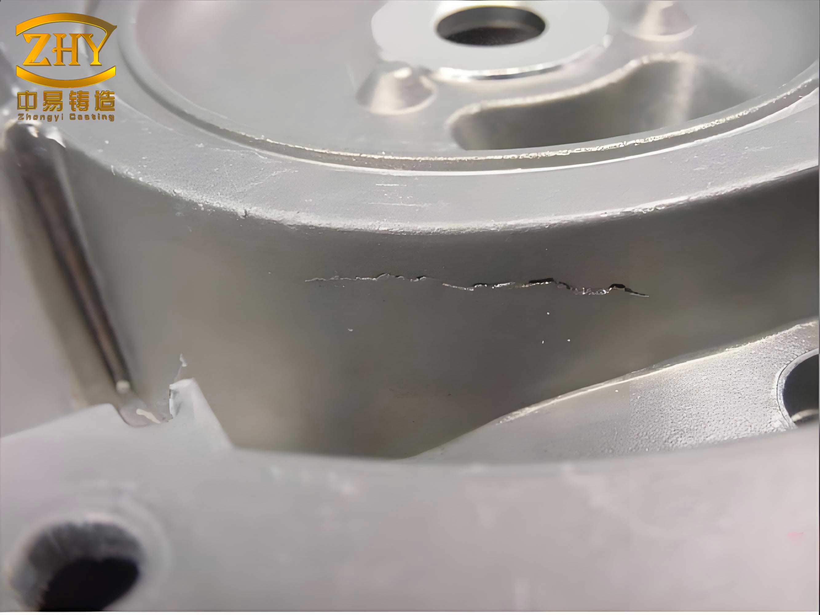
The risk of casting defects being replaced by welding defects is high. Cracking is the most critical failure mode. It originates from two synergistic factors:
- Metallurgical Stress: The transformation to martensite or white iron in the HAZ is accompanied by a volumetric expansion. However, upon cooling, the overall contraction of the weld metal and the restrained HAZ generates immense tensile stress.
- Thermal Stress: The localized intense heat input creates steep temperature gradients. The resultant thermal stress ($\sigma_{th}$) can be conceptually related to the temperature difference ($\Delta T$), the coefficient of thermal expansion ($\alpha$), and the material’s modulus of elasticity (E) by: $$ \sigma_{th} \propto E \cdot \alpha \cdot \Delta T $$
The brittle white iron and martensitic zones, with very low ductility, cannot accommodate these stresses, leading to cold cracks, often propagating from the fusion line. The problem is more pronounced in SGI than in gray iron because the spherical graphite nodules do not provide the same damping effect against crack propagation as the flake graphite network in gray iron.
2. Strategic Selection of Filler Metal
The choice of welding electrode is the first and most crucial step in mitigating the aforementioned challenges. The goal is to deposit a weld metal that is soft, ductile, and has a low propensity for hardening, thereby absorbing strain and reducing stress concentration. Austenitic nickel-based electrodes are the standard choice for high-quality arc cold welding of cast iron.
The following table summarizes the rationale behind selecting a pure nickel electrode (AWS ENi-CI, comparable to Z308) over other options:
| Electrode Type | Core Composition | Advantages for SGI Repair | Disadvantages/Risks |
|---|---|---|---|
| Pure Nickel (ENi-CI) | >90% Ni | • Maximizes graphite precipitation, minimizing carbide formation. • Excellent ductility absorbs thermal stresses, reducing crack risk. • Produces a machinable weld deposit. • Lower melting point reduces heat input and dilution. |
• Higher cost. • Potential for solidification cracking if procedure controls are poor (e.g., high dilution). |
| 55% Nickel-Iron (ENiFe-CI) | ~55% Ni, ~45% Fe | • Good ductility and strength. • Better thermal expansion match to base iron than pure Ni, reducing stress. |
• Higher dilution can increase hardness in the weld metal compared to pure Ni. • Slightly higher crack sensitivity in constrained joints. |
| Ferro-Nickel | High Fe, Ni alloyed | • Lower cost. • Good color match after machining. |
• Higher hardness in HAZ and weld metal. • Greater risk of cold cracking, especially in thick sections. |
| Mild Steel (Not Recommended) | Carbon Steel | Low cost, readily available. | • Extremely high carbon pickup from base metal, forming very hard, crack-sensitive welds. • Essentially guarantees a non-machinable, cracked repair. |
For the repair of the engine block, a 3.2 mm diameter ENi-CI electrode was selected. The nickel-rich deposit remains austenitic at all temperatures, is soft, and allows carbon to precipitate as graphite rather than forming carbides, even with some dilution from the base metal. However, a key procedural imperative is to minimize dilution to prevent excessive carbon, sulfur, and phosphorus from the base metal from entering the weld pool and forming low-melting-point eutectics that promote hot cracking.
3. Development and Implementation of the Welding Procedure
A successful cold weld repair is 90% preparation and procedure control. The following step-by-step protocol was established, embodying the principles needed to avoid introducing new casting defects in the form of weld cracks or porosity.
3.1 Defect Preparation
All defective material must be completely removed. The cavity is shaped using rotary grinders to ensure:
• Smooth, rounded contours with no sharp corners or notches (which act as stress concentrators).
• A clean, contaminant-free surface. All traces of oil, grease, moisture, and oxidation must be removed by solvent cleaning followed by grinding to bright metal.
• Verification via liquid penetrant testing (PT) to confirm the complete absence of the original casting defects.
3.2 Initial Welding Parameters and Technique
The welding is performed using Direct Current Electrode Positive (DCEP, or reverse polarity). The core parameters and techniques for the initial procedure were:
| Parameter | Setting/Rule | Technical Rationale |
|---|---|---|
| Electrode Diameter | 3.2 mm | Provides better control and lower heat input per pass than larger diameters for a cavity of this size. |
| Welding Current | 90 – 110 A | Low current minimizes arc force, penetration, and base metal dilution. |
| Arc Length & Manipulation | Short arc, minimal to no weaving. | Further reduces heat input and prevents excessive melting of the base iron walls. |
| Deposition Strategy | Short, stringer beads (max 30-40mm). | Limits heat buildup in any one area. |
| Stress Relief | Immediate peening of each bead while still warm using a small needle scaler or peening hammer. | Induces plastic deformation in the weld bead, relieving residual tensile stresses. Peening also slightly work-hardens the soft nickel weld metal, increasing its yield strength. |
| Interpass Cleaning | Thorough wire brushing after peening. | Removes slag and oxides that could cause inclusions in the next pass. |
Despite adhering to this scientifically sound initial procedure, a post-weld liquid penetrant inspection conducted 24 hours after repair revealed linear indications at the fusion boundary. This was a critical learning moment: the procedure controlled dilution and weld metal composition but did not adequately manage the thermal stress history of the entire repair zone.
4. Procedure Refinement: The Critical Role of Interpass Temperature Control
Analysis concluded that while individual beads were small, the cumulative heat input from sequential passes, without sufficient cooling intervals, raised the temperature of the entire local repair area (including the surrounding base metal) significantly. The subsequent uncontrolled air cooling of this heated volume acted like a local normalizing or even quenching cycle, generating severe thermal stresses that exceeded the strength of the HAZ, causing it to crack.
The refined procedure introduced a decisive control parameter: Maximum Interpass Temperature.
Refined Step 3 (replacing the initial version): Using DCEP at 90-110A, deposit short stringer beads. After depositing each bead, immediately peen thoroughly. Clean the bead with a wire brush. Then, allow the weld area to cool to a temperature between 50°C and 60°C (122°F – 140°F) as measured by a portable infrared thermometer, before initiating the next bead. Continue this sequence of bead → peen → clean → cool until the cavity is filled. Upon completion, insulate the entire repaired area immediately using ceramic fiber blankets to facilitate very slow cooling to room temperature.
The scientific basis for this refinement can be explained through the concept of thermal stress superposition. The total stress ($\sigma_{total}$) at the fusion line is a cumulative function of the stress from each thermal cycle:
$$ \sigma_{total} = \sum_{i=1}^{n} f(\Delta T_i, t_i, C_i) $$
where for the i-th weld bead, $\Delta T_i$ is the temperature change, $t_i$ is the cooling time, and $C_i$ is the constraint condition. By enforcing a low interpass temperature, we effectively reset $\Delta T_i$ for each new bead to a lower starting point. This prevents the progressive buildup of heat in the component’s thermal mass. The cooling rate after the final bead is also drastically reduced by insulation, moving the process closer to a furnace-cool scenario, which minimizes the final $\Delta T_n$ and thus the terminal stress $\sigma_n$.
This refinement transformed the outcome. A second repair executed with strict interpass temperature control and post-weld insulation passed the 24-hour liquid penetrant inspection without any indications. Subsequent ultrasonic testing confirmed sound internal integrity and good fusion. The engine was assembled and passed all operational tests, validating the repair.
5. Generalized Protocol and Key Learnings
Based on this and similar experiences, a robust general protocol for arc cold welding repair of major casting defects in large SGI castings can be summarized in the following flowchart table:
| Phase | Action | Key Performance Indicator / Control |
|---|---|---|
| 1. Preparation & Analysis | Defect Removal & Shaping | Cavity with smooth radii, PT-verified clean. |
| Material Identification | Confirm SGI grade (e.g., QT400). | |
| Procedure Selection | Choose arc cold welding with Ni-base electrode. | |
| 2. Welding Execution | Equipment Setup | DC+ polarity. Secure grounding away from repair zone. |
| Parameter Setting | Low current (e.g., 90-120A for 3.2mm). | |
| Deposition Technique | Short stringer beads, no weaving. | |
| Interpass Procedure | Peen → Clean → Cool to ≤60°C (Monitor with IR gun). | |
| 3. Post-Weld | Controlled Cooling | Insulate repair zone immediately after final bead. |
| Inspection | NDT (PT, UT) after 24+ hours. |
The most critical insights from this work are:
- The Electrode is Necessary but Not Sufficient: While a nickel-base electrode is essential for producing a ductile, machinable weld, its success is entirely dependent on procedure controls that manage heat.
- Thermal Management is Paramount: The prevention of cracks is less about the weld metal itself and more about controlling the thermal cycle imposed on the heat-affected zone of the base casting. Enforcing a low maximum interpass temperature is the single most effective procedural control to prevent thermal stress cracking.
- Peening is a Vital In-Process Stress Reliever: It provides a mechanical means to counteract shrinkage stresses in real-time, before they can accumulate to critical levels.
- Validation is Mandatory: No repair should be considered complete without appropriate non-destructive testing after a sufficient delay to allow for any delayed cracking to occur.
In conclusion, the repair of significant casting defects in large, complex iron castings via arc cold welding is a viable and economically crucial technology. Its success hinges on a deep understanding of the metallurgical antagonisms involved—primarily the conflict between the need for fusion and the risk of generating brittle phases and high stress. By selecting a compatible filler metal and, more importantly, enforcing a disciplined, thermally-aware procedure centered on low heat input, systematic stress relief, and strict interpass temperature control, the original casting defects can be permanently eradicated without introducing catastrophic welding defects, thereby salvaging high-value components and ensuring their service reliability.