
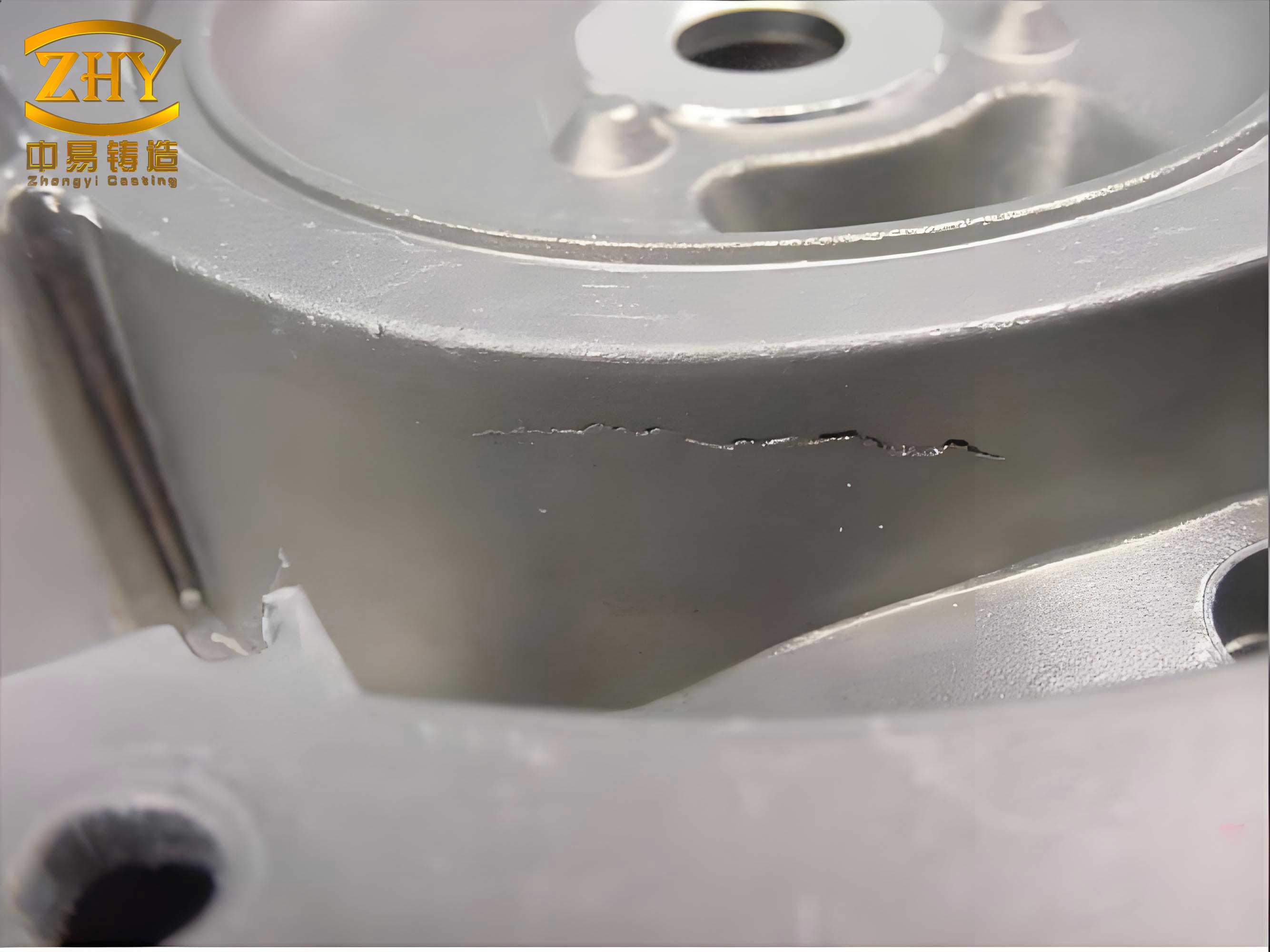
In my extensive experience within the heavy industry sector, I have frequently encountered the challenge of casting defects in large-scale components, particularly in steel ingot molds. These molds, typically made of gray cast iron with substantial wall thickness, are critical for the production of steel ingots. However, due to inherent complexities in the casting process, casting defects such as cold shuts, misruns, or more specifically, “浇不足” (insufficient pouring), often manifest on the end faces and external surfaces. These casting defects can compromise the structural integrity and service life of the molds, leading to significant economic losses if not addressed. This article details a comprehensive arc welding repair methodology developed and applied to rectify such casting defects, ensuring the molds meet stringent quality standards. The approach combines theoretical analysis, meticulous process control, and practical techniques to overcome the material limitations of gray cast iron.
The phenomenon of casting defects in ingot molds primarily stems from uncontrolled solidification dynamics, gas entrapment, or inadequate molten metal flow during the pouring stage. Specifically, the defect termed “浇不足” refers to areas where the molten metal fails to completely fill the mold cavity, resulting in surface depressions or voids. The depth of these casting defects can vary, but in severe cases, it can reach substantial magnitudes, directly affecting the mold’s dimensional accuracy and thermal fatigue resistance. Given that gray cast iron is characterized by high carbon content, low tensile strength, and negligible ductility, the presence of such casting defects creates stress concentration points that can initiate cracks under thermal cycling during subsequent use. Therefore, an effective repair strategy is not merely cosmetic but essential for restoring functional performance.
To contextualize the repair process, it is vital to understand the metallurgical behavior of gray cast iron under thermal stress. The matrix of gray cast iron consists of graphite flakes embedded in a ferritic or pearlitic iron matrix, which imparts brittleness and poor weldability. When subjected to the localized heating of welding, rapid cooling induces significant thermal gradients, leading to high residual stresses. These stresses, if not managed, can cause two primary failure modes in the weld repair zone: transverse cracks in the deposited metal and, more critically, peeling (or剥离性) cracks along the fusion line. The risk is exacerbated by the material’s low plastic deformation capacity, which cannot accommodate the strain from thermal contraction. Consequently, any welding repair for casting defects must prioritize stress mitigation through material selection and process optimization.
The fundamental principle behind crack prevention lies in balancing the thermal input and ensuring the weld metal, especially near the fusion zone, possesses sufficient ductility to relax stress. The yield strength and thermal expansion coefficients of the base metal and weld metal must be considered. A simplified model for the thermal stress ($\sigma_{th}$) generated during cooling can be expressed as:
$$\sigma_{th} = E \cdot \alpha \cdot \Delta T$$
where $E$ is the modulus of elasticity, $\alpha$ is the coefficient of thermal expansion, and $\Delta T$ is the temperature difference between the weld zone and the surrounding material. For gray cast iron, $E \approx 100-130$ GPa and $\alpha \approx 10.5 \times 10^{-6}$ /°C, leading to substantial stress even with moderate $\Delta T$. To counteract this, the weld metal should have a lower yield strength and higher ductility, allowing plastic deformation to dissipate energy. The selection of appropriate filler materials is therefore paramount.
In our practice, we employ a dual-electrode strategy to address these casting defects. The welding materials chosen are specifically designed for cast iron repair. The primary electrode for the root layer is a nickel-iron type (analogous to the mentioned ENiFe-CI or similar), which offers excellent crack resistance and good machinability. The secondary electrode for the filler layers is a high-nickel or nickel-iron-manganese type, providing enhanced ductility and strength. Both electrodes are meticulously dried according to manufacturer specifications to prevent hydrogen-induced cracking, another common issue when repairing casting defects. The table below summarizes the typical chemical composition ranges of these electrodes, which are critical for achieving compatible weld metal properties.
| Electrode Type | Nickel (Ni) % | Iron (Fe) % | Manganese (Mn) % | Carbon (C) % | Primary Application |
|---|---|---|---|---|---|
| Nickel-Iron (Root) | 45-55 | Balance | 0.5-1.5 | 0.5-1.0 | Initial layer for fusion |
| High-Nickel (Filler) | 85-95 | 2-5 | 1.0-2.5 | 0.2-0.5 | Subsequent layers for ductility |
The welding process begins with thorough pre-weld preparation, which is as crucial as the welding itself for successful repair of casting defects. All defective areas must be completely cleaned of any residual sand, oxides, or contaminants. This is achieved using grinding wheels to expose a metallic shine, ensuring optimal fusion and reducing the risk of inclusions. The geometry of the cavity left by the casting defects is also modified slightly: the edges are beveled or undercut to increase the effective bonding area and facilitate better stress distribution. This preparatory step minimizes stress concentrators that could initiate cracks post-repair.
Welding is performed using a direct current (DC) power source, with the electrode connected to the negative terminal (DC reverse polarity). This configuration provides stable arc control and deeper penetration, essential for bonding with the cast iron substrate. The heat input ($Q$) is a critical parameter controlled stringently to limit the size of the heat-affected zone (HAZ) and minimize residual stresses. It is calculated as:
$$Q = \frac{V \times I}{v} \times 60$$
where $V$ is the arc voltage in volts, $I$ is the welding current in amperes, and $v$ is the travel speed in mm/min. The factor 60 converts to joules per millimeter (J/mm). For repairing these casting defects, we maintain low heat input, typically below 10 kJ/mm, by employing small-diameter electrodes (e.g., 3.2 mm), low currents, and high travel speeds.
The welding sequence is meticulously planned to distribute heat evenly. We use a technique known as “scatter welding” or “skip welding,” where short weld beads are deposited in a dispersed pattern rather than continuously along the defect. Each bead is limited to a length of approximately 50-80 mm, after which we immediately peen the weld using a pointed hammer. Peening induces compressive stresses that counteract the tensile shrinkage stresses, effectively “stress-relieving” the weld metal plastically. The efficacy of peening can be qualitatively assessed by the reduction in residual stress, which can be modeled as a relaxation function:
$$\sigma_r = \sigma_0 \cdot e^{-k \cdot \epsilon_p}$$
where $\sigma_r$ is the residual stress after peening, $\sigma_0$ is the initial shrinkage stress, $k$ is a material constant, and $\epsilon_p$ is the plastic strain induced by peening. This practice is indispensable for preventing surface cracks in the weld metal.
For the root pass, the nickel-iron electrode is used with minimal oscillation to concentrate the arc and ensure sound fusion at the cavity bottom. The subsequent filler layers are applied with the high-nickel electrode, building up the material in a stair-step manner to avoid excessive heat buildup in any single area. Interpass temperature is rigorously monitored and kept below 150°C to prevent excessive grain growth and maintain the desired microstructure. The schematic below illustrates the layered deposition strategy for filling a typical cavity caused by casting defects.
| Layer Number | Electrode Type | Approximate Thickness (mm) | Key Function |
|---|---|---|---|
| 1 (Root) | Nickel-Iron | 2-3 | Establish bonding, crack-resistant layer |
| 2-4 (Filler) | High-Nickel | 3-4 each | Provide ductility, fill volume |
| Final (Cap) | High-Nickel | 2-3 | Smooth surface, final geometry |
The specific welding parameters for each phase are detailed in the following comprehensive table. These parameters have been optimized through iterative trials to address the unique challenges posed by casting defects in thick-section cast iron. Adherence to these parameters ensures consistent results and minimizes the occurrence of secondary casting defects induced by the repair process itself, such as porosity or lack of fusion.
| Welding Phase | Electrode Diameter (mm) | Current (I, A) | Voltage (V, V) | Travel Speed (v, mm/min) | Heat Input (Q, J/mm) | Peening Intensity |
|---|---|---|---|---|---|---|
| Root Pass | 3.2 | 90-110 | 22-24 | 120-150 | ~9.5 | Immediate, medium |
| Filler Layers | 4.0 | 130-150 | 24-26 | 180-220 | ~8.0 | Immediate, light |
| Cap Layer | 3.2 | 100-120 | 23-25 | 200-250 | ~6.5 | Optional, very light |
Post-weld treatment is straightforward but essential. After completing the weld deposition, the component is allowed to cool naturally to ambient temperature. No forced cooling is applied, as rapid cooling could reintroduce thermal stresses. Once cooled, the repaired area is ground flush with the surrounding surface using abrasive wheels. The final surface finish should be smooth to avoid any stress risers and to meet the dimensional tolerances required for the ingot mold’s function. Non-destructive testing (NDT) methods, such as dye penetrant inspection or magnetic particle testing, can be employed to verify the absence of cracks or other casting defects in the weld zone. In our applications, visual and dimensional checks have consistently confirmed the integrity of the repairs.
The success of this repair methodology hinges on a deep understanding of the thermal and mechanical interactions during welding. The cooling rate ($\frac{dT}{dt}$) in the weld zone significantly influences the microstructure and properties. For gray cast iron, avoiding the formation of hard, brittle phases like cementite in the HAZ is critical. The cooling rate can be approximated using Rosenthal’s solution for a moving heat source:
$$\frac{dT}{dt} = -2\pi k (T – T_0)^2 / Q$$
where $k$ is the thermal conductivity, $T$ is the temperature, $T_0$ is the initial temperature, and $Q$ is the heat input. By keeping $Q$ low, we reduce $\frac{dT}{dt}$, thereby minimizing the risk of martensitic transformation or excessive hardening. Furthermore, the dilution ratio, which is the proportion of base metal melted into the weld pool, must be controlled. High dilution can introduce excessive carbon from the cast iron into the weld metal, increasing hardness and crack susceptibility. The dilution ($D$) can be estimated as:
$$D \approx \frac{A_b}{A_b + A_f} \times 100\%$$
where $A_b$ is the cross-sectional area of melted base metal and $A_f$ is the area of filler metal added. Through parameter control, we maintain dilution below 30% for the root pass and even lower for subsequent layers.
In practice, we have applied this arc welding repair process to numerous steel ingot molds exhibiting various forms of casting defects. The defects, often ranging from shallow surface imperfections to deeper voids, were systematically addressed. Each repair was documented, and the molds were returned to service without any reported failures. This demonstrates the robustness of the technique. The economic impact is substantial: rather than scrapping expensive molds due to casting defects, they can be rehabilitated at a fraction of the replacement cost, extending service life and supporting sustainable manufacturing practices.
To further elaborate on the material science aspect, the choice of nickel-based electrodes is deliberate. Nickel exhibits excellent solubility in iron and promotes the formation of austenitic structures that remain ductile even at low temperatures. The nickel-rich weld metal has a lower yield strength than the base cast iron, allowing it to yield plastically under shrinkage stress, thereby protecting the fusion line from cracking. Additionally, the coefficient of thermal expansion of high-nickel alloys is closer to that of gray cast iron compared to steel fillers, reducing thermal mismatch stresses. This is quantified by the mismatch strain ($\epsilon_m$) during cooling:
$$\epsilon_m = (\alpha_{wm} – \alpha_{bm}) \cdot \Delta T$$
where $\alpha_{wm}$ and $\alpha_{bm}$ are the coefficients for weld metal and base metal, respectively. Minimizing $\epsilon_m$ is key to preventing interfacial failure.
Another consideration is the preheating requirement. While we typically avoid bulk preheating to keep the process simple and avoid distortion, localized preheating around the defect area to about 50-100°C can be beneficial for very thick sections or complex geometries. This reduces the initial thermal gradient and further mitigates stress. However, for the molds discussed, the controlled low-heat-input technique sufficed. The table below compares the effects of various preheat temperatures on the resulting hardness in the HAZ, illustrating the trade-offs.
| Preheat Temperature (°C) | Max HAZ Hardness (HV) | Risk of Cracking | Process Complexity |
|---|---|---|---|
| None (Ambient) | 350-400 | Moderate (with peening) | Low |
| 50-100 | 300-350 | Low | Medium |
| 150-200 | 250-300 | Very Low | High |
Throughout this repair work, the term casting defects remains central, as it encapsulates the origin of the problem and the target of our intervention. These casting defects are not merely surface flaws but potential initiation sites for catastrophic failure under cyclic thermal loading. By employing a disciplined welding approach, we transform these defective zones into sound, reliable metal. The process also highlights the importance of interdisciplinary knowledge, combining foundry science, welding engineering, and materials physics to address real-world industrial challenges.
In conclusion, the arc welding repair of casting defects in gray cast iron steel ingot molds is a viable and effective solution when executed with precision. The methodology outlined—encompassing careful pre-weld preparation, strategic selection of ductile filler metals, stringent control of welding parameters, and diligent peening—ensures that the repaired molds perform equivalently to defect-free ones. This approach has been validated through successful field applications, turning what would be scrap into serviceable assets. As manufacturing industries continue to seek efficiency and sustainability, such repair techniques for casting defects will remain indispensable, underscoring the adage that “prevention is better than cure,” but when casting defects occur, a well-engineered cure is invaluable.