
The integrity and dimensional stability of the machine tool casting form the foundational bedrock of modern manufacturing precision. As the silent, stalwart backbone of machining centers, lathes, and mills, these cast components are subjected to significant static and dynamic loads. The relentless pursuit of higher machining accuracy, faster production speeds, and improved surface finishes has placed unprecedented demands on these foundational elements. The industry’s trajectory has shifted from traditional, lower-strength grades towards the widespread adoption of medium-high strength (e.g., HT250, HT300) and high-strength (e.g., HT350, ductile iron) grades of machine tool castings. This evolution necessitates not only advanced foundry techniques but also robust and reliable methods for rectifying the inevitable casting defects such as sand inclusions, gas porosity, shrinkage cavities, and cracks that arise during production. Repair welding, therefore, transitions from a mere corrective measure to a critical, value-preserving technology essential for maintaining the economic viability and performance standards of these high-value components.
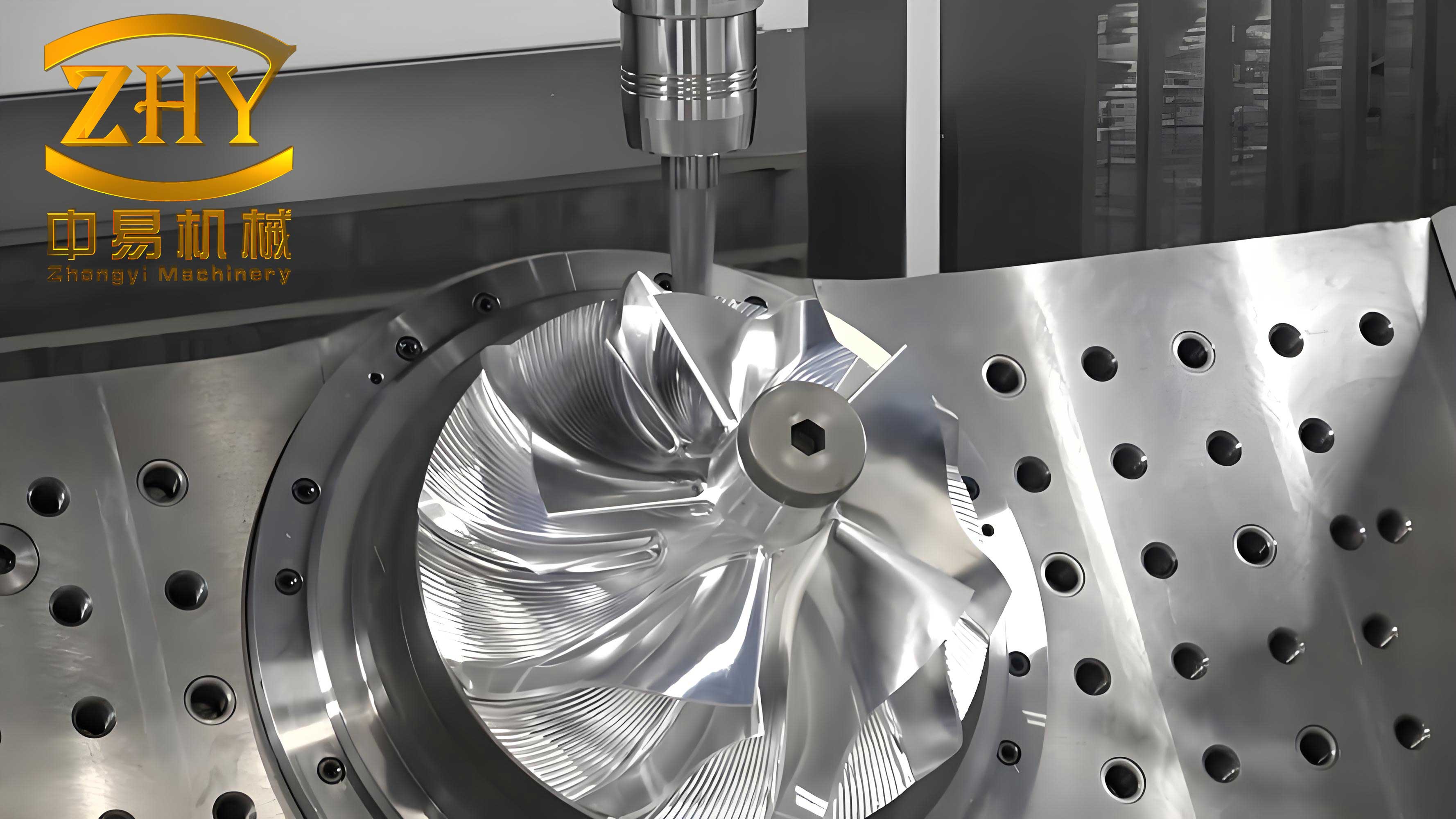
Welding Metallurgy of Grey Iron Machine Tool Castings
The primary challenge in welding any machine tool casting based on grey iron lies in its inherent metallurgical structure. Grey iron is a composite material where the graphite flakes are suspended in a metallic matrix, typically pearlite. This structure grants excellent damping capacity and good machinability but poor ductility. The welding process locally remelts and rapidly recools the material, disrupting this equilibrium and pushing the system into metastable, undesirable phases.
The core issue is the suppression of graphite precipitation and the promotion of cementite (Fe3C) formation. In the fusion zone and the adjacent heat-affected zone (HAZ), the rapid cooling associated with most welding processes does not allow sufficient time for carbon to diffuse and precipitate as graphite. Instead, carbon remains in solution in austenite and, upon further cooling, forms hard, brittle cementite. This leads to the formation of white iron (ledeburite) and hard phases like martensite in critical regions of the weld joint. The hardness of these zones can exceed 500 HBW, rendering them unmachinable and prone to cracking.
The welding thermal cycle creates distinct microstructural zones, as summarized in the table below for a typical HT250 grade machine tool casting.
| Zone | Temperature Range | Microstructural Characteristics |
|---|---|---|
| Fusion Zone (Weld Metal) | > 1250 °C | Homogeneous filler: Ledeburite (eutectic cementite) + secondary cementite + pearlite, i.e., essentially a white iron structure. Heterogeneous filler (e.g., nickel-base): High-carbon martensite under fast cooling. |
| Partially Melted Zone | 1150 – 1250 °C | A mixture of white iron and hardened (martensitic/bainitic) structures. This is often the most brittle region. |
| Austenitized Zone | 820 – 1150 °C | Upon fast cooling, secondary cementite may precipitate from austenite. Subsequent transformation can yield pearlite, bainite, or martensite depending on the cooling rate and composition. |
| Recrystallization Zone | 780 – 820 °C | Partial transformation of the matrix, resulting in refined pearlite or, if cooled quickly, martensite. |
The propensity for white iron formation is governed by cooling rate and composition. The critical cooling rate $V_{cr}$ to avoid white iron can be conceptually related to the carbon equivalent (CE) and the graphitization potential. A simplified kinetic model considers the diffusion-controlled growth of graphite:
$$ r_G(t) = \int_0^t D_C(T(\tau)) \cdot \nabla C(\tau) d\tau $$
where $r_G$ is the graphite radius, $D_C$ is the diffusivity of carbon in austenite (strongly temperature-dependent), and $\nabla C$ is the carbon concentration gradient. Rapid cooling shortens the time $t$ available for diffusion and increases the undercooling, favoring the direct formation of cementite, whose nucleation barrier $\Delta G^*_{cem}$ is lower than that for graphite $\Delta G^*_{G}$ under high undercooling:
$$ \Delta G^* \propto \frac{\gamma^3}{\Delta G_v^2} $$
where $\gamma$ is the interfacial energy and $\Delta G_v$ is the volumetric free energy change. For cementite, $\gamma_{cem/Fe}$ is lower than $\gamma_{G/Fe}$, making it the kinetically favored phase.
Cracking Mechanisms in Welded Machine Tool Castings
The second major challenge is cracking, which manifests as either cold cracks or hot cracks. The poor ductility and low tensile strength of the grey iron base material, combined with the high hardness of the transformed zones, create a perfect storm for fracture.
Cold Cracking: This typically occurs in the heat-affected zone (HAZ) or along the fusion boundary at temperatures below 400°C, where the iron has virtually no plasticity. The driving force is tensile stress generated by constrained thermal contraction. The risk is highest when the weld metal strength significantly exceeds that of the base metal, leading to “peeling” or “lift-off” cracks at the interface. The susceptibility can be assessed by considering the stress intensity versus the fracture toughness of the HAZ. The stress field $\sigma(x, T)$ is a complex function of the thermal gradient and joint rigidity. Cracking occurs when:
$$ \sigma_{max} \geq \sigma_{UTS}^{HAZ}(T, H) $$
where $\sigma_{UTS}^{HAZ}$ is the temperature-dependent ultimate tensile strength of the HAZ, which is itself a function of hardness (H). The hardness, in turn, is directly related to the volume fraction of martensite $f_M$:
$$ H_{HAZ} \approx H_\alpha’ \cdot f_M + H_{P} \cdot (1 – f_M) $$
where $H_\alpha’$ is martensite hardness and $H_P$ is pearlite hardness.
Hot Cracking: This occurs in the weld metal during solidification, particularly when using certain filler metals. For nickel-base electrodes, the problem arises from low-melting-point eutectics such as Ni-Ni3S2 (melting point 644°C) and Ni-Ni3P (melting point 880°C) that form due to the sulfur and phosphorus impurities from the base machine tool casting. The susceptibility index for solidification cracking often incorporates the effects of these elements. Similarly, when using carbon steel electrodes, the high dilution from the base metal introduces excessive carbon and impurities into the weld pool, forming Fe-FeS eutectics and promoting cracking.
Methodologies for Repair Welding Machine Tool Castings
The selection of an appropriate repair methodology for a machine tool casting is a multi-variable optimization problem. The decision tree must account for: the casting’s grade, size, and geometry; the type, size, and location of the defect; the post-weld requirements (machinability, color match, pressure tightness, strength); and practical constraints like available equipment and cost.
The principal methods are compared in the table below:
| Welding Method | Filler Material | Machinability | Density/ Sealing | Hot Crack Tendency | Cold Crack Tendency | Key Applications & Notes |
|---|---|---|---|---|---|---|
| Manual Metal Arc (MMA) | Hot/Semi-hot (Z208, Z408 type) | Excellent | Excellent | Very Low | Very Low | Large defects, aged or poor-quality castings. Excellent match but poor working conditions, high cost. |
| Cold, Ni-base (Z308, Z408 type) | Good | Good | Low | Low | General purpose, good balance of properties and workability. | |
| Cold, Steel (E5015, etc.) | Fair | Fair | High | High | Only for non-critical, non-machinable areas. High stress. | |
| Oxyacetylene (Gas) | Cast iron rod | Excellent | Excellent | Very Low | Low (with preheat) | Excellent for thin sections, produces very slow cooling. “Heated-area” technique can reduce stress. |
| Brazing | Brass, Cu-Ni alloy | Excellent | Fair | Low | Low | Ideal for repairing surface scratches on guideways. Low thermal stress. |
| Powder Spray Fusing (Oxy-fuel) | Ni/Fe-base self-fluxing powder | Excellent | Good | Moderate | Moderate | Repair of small, shallow defects on machined surfaces. Good bonding and machinability. |
Detailed Repair Welding Processes for High-Strength Castings
Pre-Weld Preparation
Success is determined before the arc is struck. For any machine tool casting repair, preparation is paramount:
- Defect Removal: The defect must be completely excavated using machining, grinding, or carefully controlled thermal gouging. For cracks, drilling stop-holes at the extremities is mandatory to prevent propagation during gouging or welding.
- Groove Preparation: The groove should be designed to minimize the volume of deposited metal and the melting of the base material, thereby reducing dilution and stress. Tapered or U-shaped grooves are preferred over V-grooves for thicker sections to reduce the included angle.
- Cleaning: All surfaces within at least 30 mm of the groove must be free of oil, grease, paint, and sand. This is typically achieved by grinding followed by degreasing with solvents.
Hot and Semi-Hot Welding Process
This process involves preheating the entire machine tool casting or a large portion of it to between 400°C (semi-hot) and 600-700°C (full hot). The goal is to slow the cooling rate through the critical temperature range, enabling graphitization and minimizing thermal gradients.
Process Parameters & Physics: The preheat temperature $T_p$ directly influences the post-weld cooling time between 800°C and 500°C ($\Delta t_{8/5}$), a critical parameter for transformation:
$$ \Delta t_{8/5} \propto \frac{(T_p – T_0)^2}{k \cdot \rho \cdot c} \cdot Q_{net} $$
where $k, \rho, c$ are the thermal conductivity, density, and specific heat of the casting, $T_0$ is ambient temperature, and $Q_{net}$ is the net heat input. A long $\Delta t_{8/5}$ promotes the diffusion-controlled reaction: Fe3C → 3Fe(γ) + C(graphite). High heat input is used, with a recommended current $I$ (in Amperes) for iron-powder type electrodes often calculated as:
$$ I = (40 \text{ to } 50) \times d $$
where $d$ is the electrode diameter in mm. Welding is performed with the casting positioned to allow uphill or flat-position welding. Interpass temperature must be maintained above the preheat level. Post-weld, the casting is covered with insulating material or, for critical components, subjected to a controlled furnace cool-down or stress relief anneal at 550-600°C.
Cold Welding Process with Non-Iron Fillers
This is the most common workshop technique for repairing machine tool castings, emphasizing strict control of heat input and weld bead sequence to manage stress.
Key Techniques:
- Short Bead, Intermittent, Dispersed Welding: Each bead is limited to 10-40 mm in length. After depositing a bead, one must wait for the area to cool to a touch-warm temperature (~50-60°C) before proceeding. Welding is distributed across different parts of a large groove to avoid localized heat buildup.
- Peening: Each small bead (except the root and final cap passes) is immediately peened while hot (>400°C) using a small, round-nosed tool. This mechanically work-hardens the surface layer, inducing compressive stress $\sigma_{comp}$ which counteracts the tensile welding stress $\sigma_{tensile}$:
$$ \sigma_{residual} = \sigma_{tensile} + \sigma_{comp} $$
Effective peening can make $\sigma_{residual}$ neutral or even compressive. - Welding Sequence Strategy: For multi-pass welds, the sequence is critical to avoid “building up” stress. A “step-back” or “cascade” technique is used. The first layer is often laid as a series of separated short beads. Subsequent layers are used to “bridge” and connect these islands, effectively distributing the contraction stresses.
The dilution, or the fraction of base metal in the weld $X$, must be minimized when using non-graphitizing fillers:
$$ X = \frac{A_b}{A_b + A_f} $$
where $A_b$ and $A_f$ are the cross-sectional areas of melted base metal and filler metal, respectively. Minimizing $X$ reduces the carbon and impurity pickup in the weld metal, directly lowering the risk of hard zones and hot cracking.
Process Selection Guidelines
The following table provides generalized guidance for selecting a repair method based on the location and requirements of the defect on a machine tool casting.
| Repair Location & Requirement | Recommended Primary Method | Alternative Methods |
|---|---|---|
| Guideway Surfaces (Sliding, as-cast) | MMA Hot Welding with铸铁芯 electrodes; Gas Welding with铸铁 rod. | MMA冷焊 with Ni-Cu or Ni-Fe electrodes (requires precise control). |
| Guideway Surfaces (Sliding, machined) | MMA冷焊 with Ni-Cu or Ni-Fe electrodes. | Brazing for shallow scratches. |
| Sealed Joints (As-cast) | MMA Hot Welding; Gas Welding. | MMA冷焊 with Ni-Fe electrodes. |
| Non-Critical Areas, No machining | MMA冷焊 with low-cost electrodes (e.g., steel). | Any method, prioritized by cost. |
Conclusion and Technical Outlook
The repair welding of high-strength machine tool castings is a demanding but fully manageable task when approached with a sound understanding of the underlying metallurgical principles. The central conflict between the desired stable graphite structure and the metastable hard phases formed during welding can be resolved through strategic process selection. This choice hinges on a critical evaluation of the casting’s service condition, the defect’s nature, and the final performance requirements. Whether employing the slow, controlled methodology of hot welding with its excellent metallurgical match, or the agile, localized technique of cold welding with specialized nickel-base fillers, success is governed by meticulous preparation, disciplined control of heat input and thermal cycles, and adherence to stress-relieving practices like strategic bead sequencing and peening. As the performance demands on the machine tool casting continue to escalate, so too will the sophistication of repair welding techniques, potentially incorporating advanced processes like laser powder deposition or friction stir welding for specific, high-value applications, ensuring the longevity and precision of these fundamental components of industry.