
The successful production of high-integrity, heavy-section machine tool castings represents a significant achievement in foundry engineering. These components form the structural backbone of large machining centers, such as floor-type boring mills, and their quality directly dictates the machine’s accuracy, stability, and longevity. This article details the comprehensive research and development process undertaken for a critical heavy machine tool column, focusing on the systematic approach to process design, simulation, and controlled execution to eliminate defects and meet stringent specifications.
The subject of this development was a large vertical column, a quintessential heavy machine tool casting. Its specifications presented formidable challenges: a contour dimension of 7,120 mm in height, 2,760 mm in width, and 2,820 mm in depth, with a main wall thickness of 40 mm and locally thickened guide rail sections of 160 mm. The material specification was HT300 (a high-strength gray iron), with a final rough casting weight of approximately 59 tonnes. The primary requirements were exceptional density and soundness in the guide rail surfaces, with a complete absence of shrinkage cavities, porosity, gas holes, and—most critically—cracks. The sheer size and the structural configuration, featuring a large internal cavity surrounded by reinforcing ribs creating a “回”-shaped section (a closed-box-like structure), inherently promoted high thermal stress and restrained contraction, making crack prevention the paramount concern.
1. Foundry Process Design and Strategy
The foundation of producing flawless heavy machine tool castings lies in a robust and meticulously planned foundry process. Every decision, from the molding method to the design of reinforcement, was made with the dual objectives of facilitating sound solidification and managing stress.
1.1 Molding Scheme and Pattern Design
Given the component’s massive size, a pit molding method was employed. This utilized a large, prepared sand bed within the foundry floor as the lower drag. The pattern was strategically designed as a combination of loose pieces and withdrawable cores to minimize draft and facilitate molding. Ample venting channels were placed at the bottom and sides of the pit to ensure gases could escape efficiently during the pour.
1.2 Feeding and Chilling Strategy
Due to the relatively uniform wall thickness and the planned use of a controlled pouring system, conventional feeding risers were not placed directly on the main body of this machine tool casting. Instead, small venting risers (φ40 mm) were used to aid atmosphere displacement. However, to compensate for liquid shrinkage and ensure a full mold, specially designed insulating risers (φ250 mm) were placed on the running system headers at both ends of the casting for post-pour feeding. To promote directional solidification and achieve the required high hardness on the critical guideways, graphite blocks (80 mm thick) were used as chills, placed directly on the mold cavity at the guide rail locations.
1.3 Core Design and Venting
The complex internal geometry necessitated over 60 individual sand cores, with some exceeding one tonne in weight. Each core was meticulously engineered with strong core prints. Crucially, an extensive network of venting was incorporated. Vent tubes were installed before core filling, connected internally to nylon vent ropes, which in turn linked to external vent channels. This multi-path system was essential to prevent core gas defects in such a voluminous machine tool casting.
1.4 Proactive Measures to Prevent Casting Cracks
The “closed-box” structural motif is a notorious stress concentrator. Our primary countermeasures focused on the relatively slender top section of the column, identified as the most crack-prone zone. A multi-pronged approach was implemented:
- Structural Reinforcement: The top wall thickness was increased from 40 mm to 60 mm. Furthermore, additional internal reinforcing ribs (140 mm wide x 45 mm thick) were added on all four interior walls connecting to the top section. This served a dual purpose: it increased the fracture strength of the region and, by adding thermal mass, modestly slowed the cooling rate, reducing thermal gradients and stress.
- Controlled Cooling: A strict cooling protocol was mandated. The casting was required to cool in the closed mold until its temperature fell below 180°C before shakeout. Forced cooling with air was prohibited to avoid inducing excessive thermal stress.
- Metallurgical Adjustment: The melt chemistry was tailored to lower residual stress. This involved optimizing the carbon equivalent (CE) and increasing the silicon-to-carbon ratio, which promotes the formation of graphite and reduces the shrinkage tendency of the iron, thereby lowering internal stress in the final machine tool casting.
The key process parameters for crack prevention are summarized below:
| Measure | Target/Parameter | Intended Effect |
|---|---|---|
| Top Wall Thickness | Increase from 40mm to 60mm | Increase sectional modulus & fracture strength |
| Internal Ribs | Add 140×45 mm ribs | Reinforce structure & moderate cooling |
| Shakeout Temperature | < 180 °C | Allow stress relaxation, avoid quench stress |
| Cooling Method | Natural cooling only | Prevent thermal shock |
| Si/C Ratio | Adjusted upward | Promote graphite formation, reduce stress |
2. Gating System Design for Heavy Castings
The design of the gating system for a massive machine tool casting is governed by the principle of “high flow rate, low velocity, and smooth, clean filling.” The goal is to establish the most uniform temperature field possible within the mold cavity upon complete filling.
2.1 Pouring Position and System Layout
To manage the enormous volume of metal required (approximately 70 tonnes of liquid iron), a simultaneous three-ladle pour was planned. The running system was designed as a C-shaped header that partially encircled the casting. Multiple downsprue bases were connected to this header, which then fed a distributed network of in-gates. This layout aimed to introduce metal at numerous, evenly spaced points to avoid localized hot spots and minimize dynamic pressure during filling.
2.2 Determination of Gating System Cross-Sections
For tall, heavy-section gray iron castings like this column, a choke-control gating system (initially pressurized, then open) is often advantageous. It aids in slag trapping and promotes smoother filling. The choke point was set at the downsprue. The area ratios for the system were designed as follows:
$$ \sum A_{sprue} : \sum A_{choke} : \sum A_{runner} : \sum A_{gate} = 0.3 : 1.0 : 1.4 : 2.1 $$
Based on this ratio and practical considerations for flow distribution, the final system was constructed with:
- 6 downsprue wells (φ100 mm each)
- 28 choke sprues (φ40 mm each)
- 84 in-gates (φ40 mm each)
The actual calculated cross-sectional areas were:
$$ \sum A_{choke} = 28 \times \pi \times (20 \text{ mm})^2 = 28 \times 1256.6 \text{ mm}^2 \approx 35185 \text{ mm}^2 = 351.9 \text{ cm}^2 $$
$$ \sum A_{gate} = 84 \times \pi \times (20 \text{ mm})^2 = 84 \times 1256.6 \text{ mm}^2 \approx 105554 \text{ mm}^2 = 1055.5 \text{ cm}^2 $$
$$ \sum A_{sprue} = 6 \times \pi \times (50 \text{ mm})^2 = 6 \times 7854 \text{ mm}^2 \approx 47124 \text{ mm}^2 = 471.2 \text{ cm}^2 $$
The consistency with the designed ratio verifies the layout’s adherence to the intended flow characteristics for this large machine tool casting.
| Gating Element | Quantity & Dimension | Total Cross-Sectional Area (cm²) |
|---|---|---|
| Downsprue | 6 x φ100 mm | 471.2 |
| Choke / Secondary Sprue | 28 x φ40 mm | 351.9 |
| In-Gate | 84 x φ40 mm | 1055.5 |
3. Melting and Metallurgical Process Control
The quality of the base iron is fundamental to the performance of any machine tool casting. The strategy emphasized high melt rates and minimal holding time to preserve superheat and minimize gas pickup.
- Melting Setup: Two 20-tonne medium-frequency induction furnaces were operated in tandem. A total of 70 tonnes of iron was prepared and held in one 30-tonne and two 20-tonne ladles to facilitate the triple-pour operation.
- Chemical Composition: The target chemistry for the HT300 grade was tightly controlled to ensure strength while maintaining good casting properties. Analysis was performed using a spectroscope for rapid feedback.
| Element | Target Range (wt.%) |
|---|---|
| C | 3.0 – 3.1 |
| Si | 1.6 – 1.8 |
| Mn | 1.0 – 1.1 |
| Cr | 0.25 – 0.30 |
| Cu | 0.5 – 0.6 |
- Charge Materials: Raw materials were carefully selected. The scrap steel charge was maintained at no less than 40% to provide a clean, low-inheritance base iron.
- Melt Treatment: The iron from one furnace was subjected to a high-temperature refining cycle at approximately 1500°C for a short duration to aid in deoxidation, degassing, and slag removal.
4. Pouring and Solidification Process Control
The final phase of creating a sound heavy machine tool casting is the precise execution of the pour and subsequent solidification management.
- Inoculation Practice: A multi-stage inoculation sequence was employed to maximize graphite nucleation and ensure consistent microstructure throughout the massive section: furnace or spout inoculation, followed by ladle inoculation, and finally, instant inoculation in the pouring bush.
- Ladle Treatment and Pour Initiation: All three ladles underwent slag skimming/raking before the pour. The bushings for each ladle’s stream were fitted with stoppers. The pour commenced only after all pouring cups were filled, at which point the stoppers were raised simultaneously to prevent initial slag from entering the mold.
- Pouring Dynamics: The pour followed a “fast-slow” sequence. A rapid initial fill was used to avoid mistruns. As the metal level approached the top of the mold, the flow rate was deliberately reduced to a slow, steady stream. This prevented excessive turbulence and allowed trapped mold gases to vent, eliminating issues like blowouts or runouts.
- Critical Parameters: Tight control was maintained over key variables to prevent cold shuts and ensure complete filling.
| Parameter | Target Value |
|---|---|
| Pouring Temperature | 1360 ± 10 °C |
| Total Pouring Time | 140 – 170 seconds |
- Post-Pour Feeding: Immediately after the mold was filled, the insulating risers on the headers were repeatedly topped up with hot metal until the liquid level remained stable, ensuring adequate feed metal was available to compensate for liquid shrinkage.
5. Production Validation and Results
Prior to committing to the full-scale production of this costly heavy machine tool casting, the entire process was validated through computational simulation. Both mold filling and solidification analyses were conducted. The simulations helped visualize potential hotspots, feeding efficiency, and areas of high stress concentration. Minor adjustments, particularly to chill placement and venting layout, were made based on the simulation feedback.
The casting was subsequently produced according to the finalized process. After the mandated slow cooling cycle, the casting was shaken out. Non-destructive examination revealed a sound casting with no visible defects. The final and most critical validation occurred during machining. The guide rail surfaces were machined to a finish, revealing a dense, homogeneous microstructure with no subsurface shrinkage, porosity, or cracks. The casting fully met all dimensional and property specifications for the demanding application.
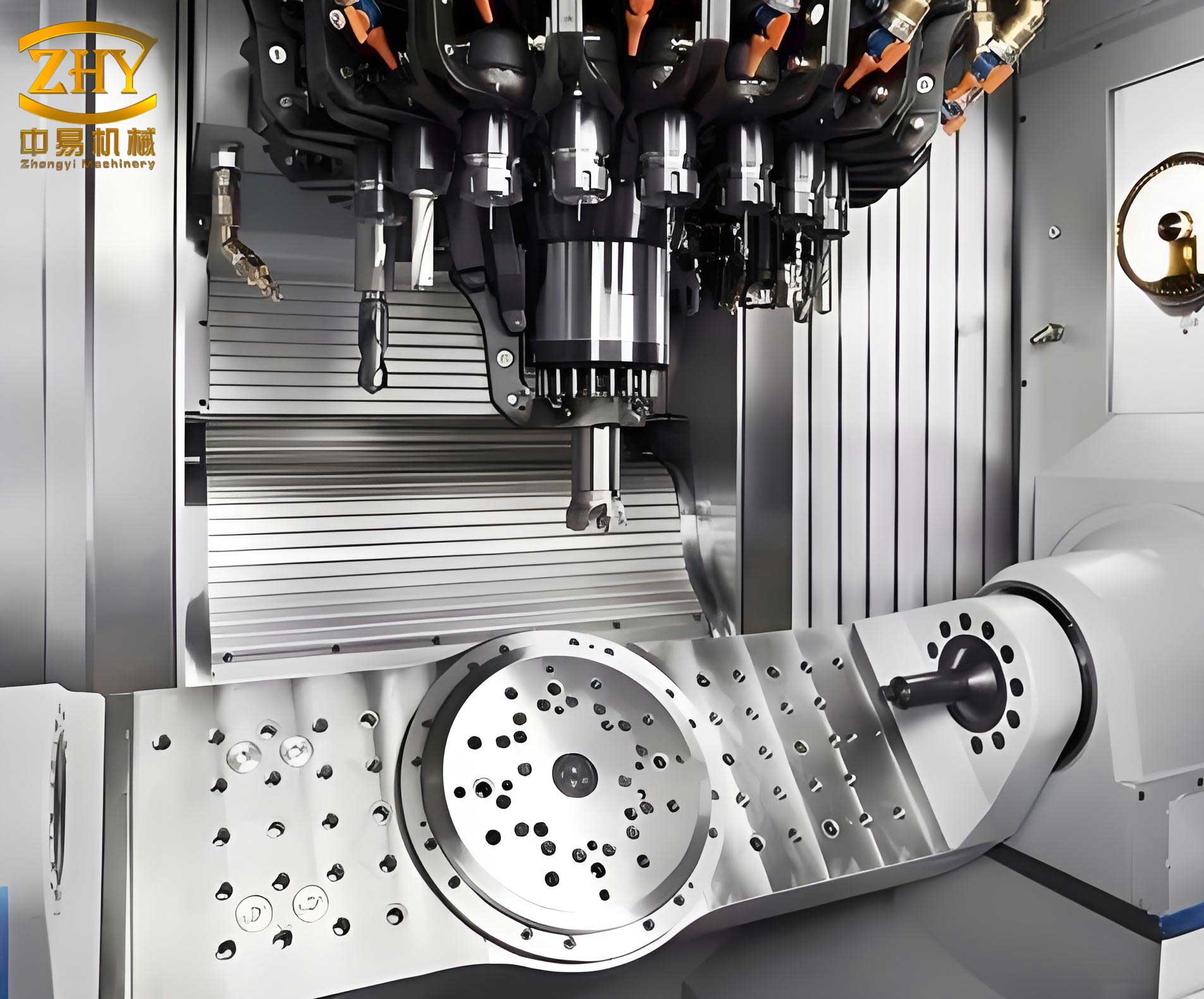
In conclusion, the successful development of this heavy machine tool casting was the result of a holistic and integrated approach. Key to success was the proactive design of the casting process to manage thermal stresses and prevent cracking, the rational design of a multi-point gating system to ensure uniform filling, stringent control over metallurgy and melt quality, and precise execution of the pouring sequence. The use of solidification simulation proved invaluable as a verification tool. The outcomes demonstrate that with meticulous planning and control, it is feasible to produce massive, complex machine tool castings of the highest integrity, capable of serving as the reliable foundation for precision heavy machinery.