
With the ongoing adjustments in national industrial policies, the demand for machine tool products has surged, particularly for high-precision CNC machine tools, which represent a significant growth area. Historically, such advanced machine tool products were often imported, with those featuring high technical content facing strict restrictions from foreign sources. In response, our company initiated a comprehensive product restructuring in 2000, focusing on market orientation, profitability, quality assurance, and innovation-driven development. We have deeply adjusted our product portfolio, leveraging high technology and implementing a brand strategy to enhance competitiveness.
Currently, our independently developed vertical and horizontal heavy-duty CNC lathes are recognized as national brand products, with multiple items receiving national awards for scientific and technological progress. We supply critical equipment to sectors including defense, transportation, and metallurgy, positioning our company among the top machinery enterprises in China. As a manufacturer of high-precision, technologically advanced CNC machine tools, we impose stringent requirements on machine tool castings. Certain castings must exhibit high strength, precision, wear resistance, and other technical properties, while dimensional accuracy, internal cleanliness, surface roughness, and metallurgical quality are critically important. To ensure the quality of these machine tool castings, we have conducted extensive process studies on key components such as columns, worktables, beams, beds, and boxes for vertical and horizontal machine tools.
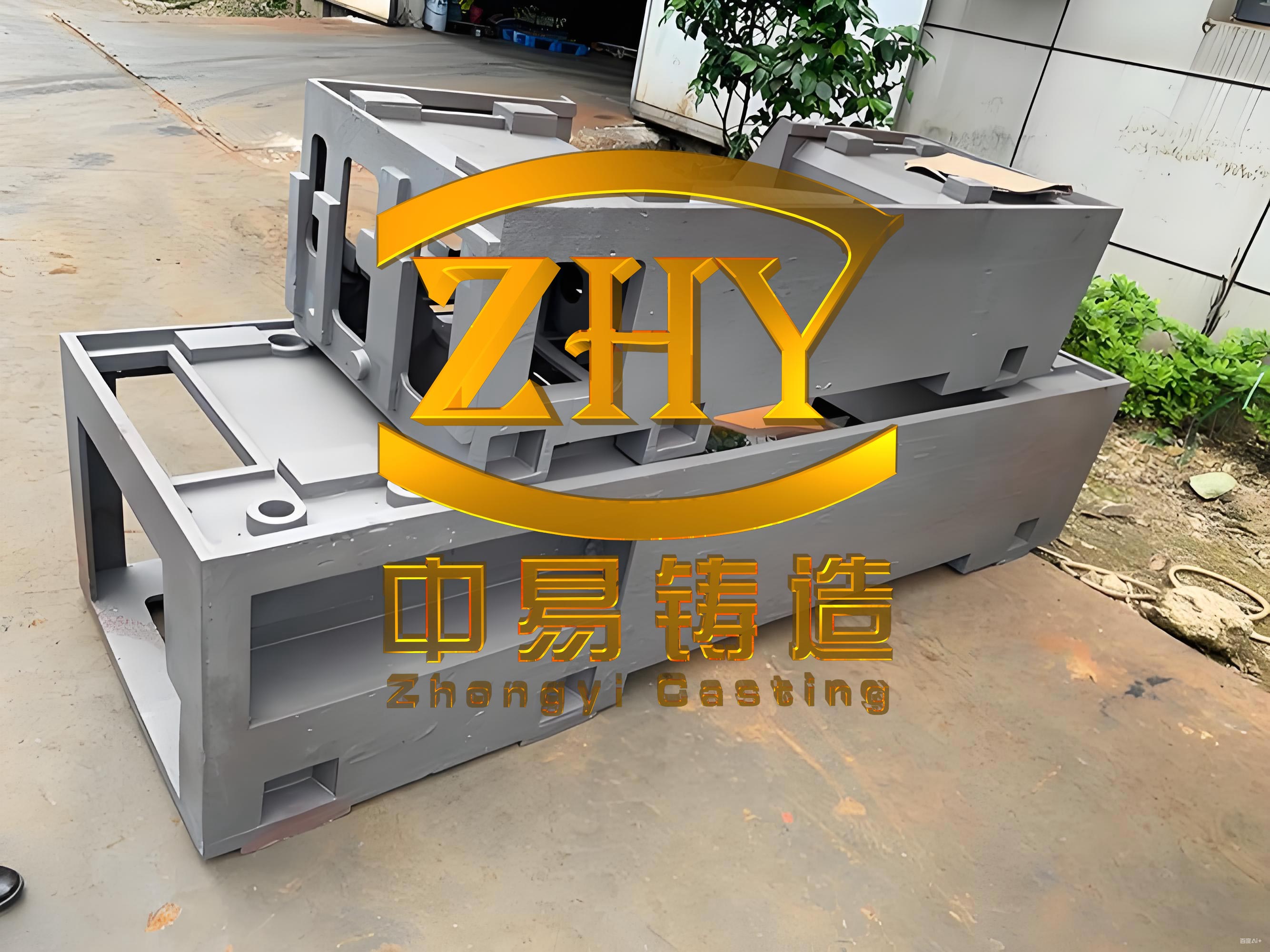
The production of beam, column, and bed castings involves specific challenges due to their large sizes and high precision requirements. These machine tool castings feature guideways that must achieve accuracies within 0.02 mm/m after machining, necessitating high strength, wear resistance, and hardness above 190 HB. The guideway areas must be free of any defects, as even minor imperfections can compromise performance. For instance, beams and columns are typically made from grades like HT250 or HT300, with loads ranging from 1000 to 2000 kN and deflections under 0.5 mm. Given our rapid company growth and the prevalence of large vertical lathes, beam and column castings often reach lengths of 5 to 10 meters, with pouring weights between 5 and 20 tons. The largest column casting we produced had a pouring weight of 12.5 tons. These dimensions exceed our standard production capacity, as our largest foundry is equipped with only a 5-ton medium-frequency induction furnace and a 5-ton holding furnace. Producing such large machine tool castings with guaranteed quality and performance is challenging, necessitating systematic research to meet production demands.
In terms of pattern making for machine tool castings, we employ various forms, including solid patterns, core assembly patterns, and pattern plates. Beyond dimensional accuracy, patterns must be durable, which is achieved through rational structural design and adequate draft angles and surface finish to reduce pattern withdrawal resistance. To avoid dimensional errors from excessive draft angles, external patterns sometimes incorporate core-pulling structures, which also ease withdrawal and extend pattern life. Key specifications include pattern and core box strength at Grade 3, the use of a 1% shrinkage allowance for gray iron patterns and core boxes, and the selection of Grade A or B infrared-dried high-quality red pine and multi-layer plywood with moisture content below 12% and an aging period exceeding 15 days.
Core process design is crucial for the dimensional accuracy of machine tool castings and must satisfy several requirements: cores should be easy to fix and vent; the number of cores should be minimized while ensuring convenient core making; cores must facilitate setting and dimension measurement; a flat sand-filling surface is preferred; the design should allow for gating system installation and cleaning; core strength and rigidity must be ensured; and core shape, dimensions, and position in the mold must meet casting tolerance requirements. To achieve dimensional accuracy, we use cold-set furan resin sand for molding. To prevent defects like mechanical sand burning, gas holes, and veining, we add iron oxide powder to the molding sand and apply a zircon-based alcohol-fast-drying coating on mold and core surfaces, with a thickness of 0.5 mm, followed by polishing to ensure surface roughness. Additionally, we use gauges for inspection to verify dimensions before proceeding.
For the gating system in machine tool castings, we employ semi-closed bottom gating or step gating systems composed of ceramic tubes. This design promotes smooth metal flow and reduces turbulence, which is essential for high-quality machine tool castings. Regarding riser and vent design, the principles focus on ensuring that risers solidify after the casting hot spots to enhance liquid shrinkage compensation. The riser design can be guided by the modulus method, where the modulus \( M \) is defined as the ratio of volume to surface area: $$ M = \frac{V}{A} $$ For effective feeding, the riser modulus should exceed that of the casting: $$ M_{\text{riser}} > M_{\text{casting}} $$ In practice, we often use $$ M_{\text{riser}} = k \cdot M_{\text{casting}} $$ where \( k \) is a factor greater than 1, typically ranging from 1.1 to 1.2 for large machine tool castings. For vent design, to enhance overall mold排气, vents are added as needed, with the total cross-sectional area of vents generally exceeding that of the sprue to facilitate gas escape during pouring.
Quality control for guideway areas in machine tool castings is critical due to their thick sections. To ensure low shrinkage levels and refined microstructure, we use graphite chills with thicknesses of 20 to 50 mm for forced cooling. The cooling effect can be approximated by the heat transfer equation: $$ Q = h \cdot A \cdot \Delta T \cdot t $$ where \( Q \) is the heat extracted, \( h \) is the heat transfer coefficient, \( A \) is the surface area, \( \Delta T \) is the temperature difference, and \( t \) is time. For areas with significant wall thickness variations, graphite chills are also applied to promote directional solidification and prevent defects. Deflection control is another vital aspect; preventing deformation in long, complex machine tool castings requires presetting anti-deformation during molding, known as molding camber. The anti-deformation value is set empirically based on structural characteristics, such as wall thickness differences, width-to-height ratios, and internal rib layout. For bed castings, the molding camber typically ranges from 0.5 to 1.0 mm/m, while for beams, it is between 0.5 and 1.5 mm/m. In pit molding, the camber is reduced accordingly. The deflection \( \delta \) can be estimated using beam theory: $$ \delta = \frac{5 w L^4}{384 E I} $$ where \( w \) is the uniform load, \( L \) is the length, \( E \) is the modulus of elasticity, and \( I \) is the moment of inertia, though we primarily rely on experience for these large machine tool castings.
Other measures include inspecting large castings with gauges before closing the mold and using pressure beams to bind flasks to prevent mold expansion. For pit molding, the weight on the mold must be at least 1.5 times the molten metal weight to prevent lift-off, ensuring stability during pouring. These steps are integral to producing defect-free machine tool castings.
Chemical composition control is essential for achieving the desired properties in machine tool castings. For bed castings, which have thick guideways (50–150 mm) and pouring weights up to 10 tons, the structure is less prone to cracking. The chemical compositions are carefully controlled, as shown in Table 1.
| Cast Iron Grade | C | Si | Mn | P | S |
|---|---|---|---|---|---|
| HT250 | 3.1–3.5 | 1.5–2.0 | 0.8–1.2 | ≤0.15 | ≤0.12 |
| Target | 3.2 | 1.8 | 1.0 | 0.10 | 0.10 |
| HT300 | 2.9–3.2 | 1.4–1.8 | 0.9–1.2 | ≤0.15 | ≤0.12 |
| Target | 3.0 | 1.6 | 1.0 | 0.10 | 0.10 |
| HT350 | 2.8–3.1 | 1.3–1.7 | 1.0–1.4 | ≤0.15 | ≤0.12 |
| Target | 2.9 | 1.5 | 1.2 | 0.10 | 0.10 |
For beam and column castings, which are larger and more complex with higher performance requirements, careful attention is paid to prevent cracking. We have experienced issues such as premature shakeout leading to cracks in a column casting with a pouring weight of 6.5 tons, and low carbon equivalent causing deformation in a 4-ton beam. Therefore, we control carbon equivalent to avoid low values and employ alloying to ensure properties. The chemical compositions are detailed in Table 2.
| Cast Iron Grade | C | Si | Mn | P | S | Cr |
|---|---|---|---|---|---|---|
| HT300 | 2.8–3.1 | 1.4–1.8 | 0.9–1.2 | ≤0.15 | ≤0.12 | 0.2–0.4 |
| Target | 2.9 | 1.6 | 1.0 | 0.10 | 0.10 | 0.3 |
| HT350 | 2.7–3.0 | 1.3–1.7 | 1.0–1.4 | ≤0.15 | ≤0.12 | 0.3–0.5 |
| Target | 2.8 | 1.5 | 1.2 | 0.10 | 0.10 | 0.4 |
| HT400 | 2.5–2.9 | 1.2–1.6 | 1.2–1.6 | ≤0.12 | ≤0.10 | 0.4–0.6 |
| Target | 2.7 | 1.4 | 1.4 | 0.08 | 0.08 | 0.5 |
For worktable and box castings, which have simpler shapes and lower shrinkage requirements, we initially faced issues with shrinkage porosity on upper surfaces. By increasing carbon equivalent, reducing pouring temperature, and adding more ingates to promote directional solidification, we achieved better results. The chemical compositions are provided in Table 3.
| Cast Iron Grade | C | Si | Mn | P | S |
|---|---|---|---|---|---|
| HT250 | 3.4–3.8 | 1.5–2.0 | 0.8–1.2 | ≤0.15 | ≤0.12 |
| Target | 3.6 | 1.8 | 1.0 | 0.10 | 0.10 |
| HT300 | 3.0–3.4 | 1.4–1.8 | 0.9–1.2 | ≤0.15 | ≤0.12 |
| Target | 3.2 | 1.6 | 1.0 | 0.10 | 0.10 |
| HT350 | 2.8–3.2 | 1.3–1.7 | 1.0–1.4 | ≤0.15 | ≤0.12 |
| Target | 3.0 | 1.5 | 1.2 | 0.10 | 0.10 |
The melting process for machine tool castings involves precise control to meet quality standards. Our production facilities include an imported spark spectrometer, digital thermometers, a 5-ton medium-frequency induction furnace, a 5-ton holding furnace, and various ladles (2-ton, 5-ton, 10-ton). In another foundry, we have two 3-ton cupola furnaces and 6-ton ladles. Charge materials consist of pig iron (e.g., L04 or L08), ordinary carbon steel scrap, low-phosphorus gray iron returns, and ferroalloys like ferrosilicon, ferromanganese, and carburizers. The charge ratios are summarized in Table 4.
| Cast Iron Grade | Pig Iron | Scrap Steel | Returns |
|---|---|---|---|
| HT200 | 40 | 30 | 30 |
| HT250 | 50 | 30 | 20 |
| HT300 | 30 | 50 | 20 |
| HT350 | 30 | 60 | 10 |
Iron melting control varies with pouring weight: for weights up to 10 tons, we use the 5-ton induction furnace and holding furnace simultaneously or employ ladle transfer; for 10–15 tons, ladle transfer is used; and for 15–50 tons, we implement duplex melting with the induction furnace and cupola. Since our heavy foundry lacks a cupola, we melt iron in the medium foundry’s 3-ton cupola and transport it to the heavy foundry for temperature adjustment and composition tuning. Specific steps include melting 5 tons in the induction furnace, with the holding furnace preheated 15 minutes in advance; when temperature reaches 1320°C, samples are taken for chemical and spark spectrometry analysis to ensure element contents like C, Si, Mn, P, and S are within deviations of ±0.05%. If carbon is low, carburizer is added with an absorption rate of 70–80%. After composition adjustment, iron is transferred between furnaces and ladles to homogenize and fine-tune properties. For larger batches, the cupola-melted iron is transported and treated in the induction furnace for heating and composition adjustment, with careful timing to avoid solidification in ladles.
High-temperature refining is performed by heating each furnace of iron above 1320°C for short periods to remove gases and impurities, enhancing the quality of machine tool castings. Enhanced inoculation involves three stages: stream inoculation during tapping with 0.3% of 3–10 mm ferrosilicon inoculant added over 70–80% of the tapping time; floating silicon inoculation after treatment with 0.15% of 20–30 mm ferrosilicon inoculant per ladle; and instant inoculation during pouring with 0.1% of 0.5–1 mm barium-bearing ferrosilicon alloy inoculant. The inoculation effectiveness can be related to the fading time, and we aim to minimize this by adding inoculants close to pouring. Iron treatment temperature control requires calculating transfer, heating, treatment, and pouring times for each ladle, with pouring temperature deviations kept within 10°C. The temperature loss during transfer can be estimated using: $$ \Delta T = \frac{h A (T – T_{\text{env}}) t}{m c_p} $$ where \( \Delta T \) is the temperature drop, \( h \) is the heat transfer coefficient, \( A \) is the surface area, \( T \) is the iron temperature, \( T_{\text{env}} \) is the environment temperature, \( t \) is time, \( m \) is mass, and \( c_p \) is specific heat capacity. By managing these factors, we ensure consistent quality in machine tool castings.
Since 2005, our company has produced numerous large machine tool castings, including two columns with pouring weights of 8.3 tons, six worktables of 9.8 tons, three columns of 7.5 tons, and fifteen beams weighing 5–10 tons. Testing confirms that properties fully meet process requirements, though two worktables initially exhibited shrinkage in risers, which was resolved by optimizing the gating system. Based on our experience, key considerations for large machine tool castings include: strictly reviewing casting structures for process suitability, as inappropriate designs can lead to defects like cracking; designing rational gating systems, such as using multi-level gating for tall castings to ensure proper solidification; implementing multi-layer inoculation to counteract fading during prolonged processing; and controlling pouring temperature with differences not exceeding 20°C for multiple ladles. These practices have proven effective in producing high-quality machine tool castings that meet the demanding standards of modern CNC machine tools.
In summary, the research and implementation of advanced casting techniques have enabled us to overcome production challenges and deliver reliable machine tool castings. Continuous improvement in process control, chemical composition, and melting practices ensures that our machine tool castings exhibit the necessary strength, precision, and durability for critical applications. As the industry evolves, we remain committed to innovation and quality in the production of machine tool castings, contributing to the advancement of high-precision machine tools.