1. Introduction
The automotive industry is constantly evolving, with the pursuit of high – quality, lightweight components becoming a key trend. ZL101A aluminum alloy, due to its excellent properties such as good fluidity, low shrinkage rate, and small hot – cracking tendency, has been widely used in the production of automotive parts, especially in the manufacturing of transmission rear covers. Low – pressure casting is a popular method for producing ZL101A transmission rear cover castings. It offers advantages like controllable filling speed and good casting formability. However, the problem of shrinkage holes in these castings remains a significant challenge, affecting the quality and performance of the final product. This paper aims to comprehensively explore the improvement process of shrinkage hole defects in ZL101A back cover castings, analyze the causes, and propose effective countermeasures.
2. Overview of ZL101A Transmission Rear Cover Castings
2.1 Casting Application and Material
The ZL101A transmission rear cover castings produced by the company are mainly used in commercial vehicle AT automatic transmissions. The material ZL101A is a commonly used casting aluminum – silicon – magnesium alloy. It provides good mechanical properties and corrosion resistance after modification, refinement, and T6 heat treatment, making it an ideal material for lightweighting commercial vehicle components.
2.2 Casting Dimensions and Structure
The casting has an outer dimension of 420 mm×410 mm×160 mm. Its structure is shown in Figure 1. The complex structure of the casting, with various thickness changes and geometric features, poses challenges during the casting process.
| Feature | Details |
|---|---|
| Dimensions | 420 mm×410 mm×160 mm |
| Shape | [Describe the general shape, e.g., with some protrusions and recesses] |
| Wall Thickness | Average 7 mm, but with significant variations |
2.3 Casting Process
The casting is produced by the metal – mold low – pressure casting process. The mold structure is shown in Figure 2. In this process, the metal liquid is filled from the bottom up, and the pressure and speed can be controlled to ensure the filling quality. However, the design of the mold and the process parameters also affect the formation of shrinkage holes.
| Mold Component | Function |
|---|---|
| Moving Mold | Forms one part of the cavity and can be separated for casting removal |
| Static Mold | Together with the moving mold, forms the complete casting cavity |
| Shunt Cone | Helps in guiding the flow of metal liquid |
| Gate Sleeve | Connects the metal liquid source to the casting cavity |
3. Shrinkage Hole Defects and Their Causes
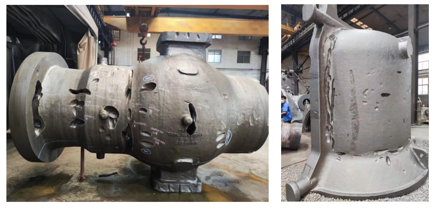
3.1 Detection and Appearance of Shrinkage Holes
The castings are inspected by X – ray flaw detection, and it is found that there are local shrinkage hole defects. Figure 3 shows the shrinkage hole defects detected by X – ray, and Figure 4 shows the anatomical shrinkage defects of the casting. The shrinkage hole defects in this part exceed the requirements of ASTM E155 standard level 3, which is unacceptable to customers.
3.2 Causes Analysis
The main reason for the formation of shrinkage holes in this part is that although the average wall thickness of the casting is 7 mm, the hot – spot diameter at this part exceeds 30 mm. During the casting process, the aluminum liquid cannot effectively compensate for the shrinkage during solidification. As a result, shrinkage holes are formed. To eliminate these defects, it is necessary to improve the feeding conditions of this part, which can be achieved by increasing local cooling or adding feeding channels.
| Factor | Impact on Shrinkage Holes |
|---|---|
| Wall Thickness Variation | Uneven wall thickness leads to different solidification rates, with thick areas (hot – spots) being more prone to shrinkage holes |
| Inadequate Feeding | Insufficient aluminum liquid supply during solidification in hot – spot areas causes shrinkage holes |
4. Improvement Measures and Analyses
4.1 Local Cooling Enhancement in the Mold
4.1.1 Modification of the Mold
Based on the mold structure characteristics, cooling inserts are added by cutting at the position of the upper mold core corresponding to the shrinkage hole part of the casting, as shown in Figure 5. There are two cooling inserts, 1# and 2#, with different cooling methods to enhance the local cooling effect.
| Insert Number | Cooling Method |
|---|---|
| 1# | Air cooling |
| 2# | Water cooling |
4.1.2 Pouring Verification and Process Parameters
After modifying the mold, pouring verification is carried out. The main idea of setting the pouring process parameters is to use a large holding pressure and a fast pouring speed to make the casting solidify under high pressure, improve the tissue density, and reduce the shrinkage hole tendency. The specific pouring process parameters are shown in Table 1.
| Process and Item | Pouring Process Parameters |
|---|---|
| Pressure/mbar | Time/s |
| First Stage (Lifting Liquid) | 220, 10 |
| Second Stage (Filling) | 320, 17 |
| Third Stage (Pressurization) | 370, 3 |
| Fourth Stage (Holding Pressure) | 370, 400±50 |
| Pouring Temperature/℃ | 720±5 |
| Cooling Time/s | 240 – 300 |
| 1# Insert Cooling Setting | Air cooling, 20 s on, 200 s off |
| 2# Insert Cooling Setting | Water cooling, 35 s on, 85 s off |
4.1.3 Results of the Test
Four shifts of continuous production are carried out, and all castings are inspected by X – ray flaw detection. The test results of the trial – produced parts are shown in Table 2.
| Shift | Number | Pouring Quantity / 件 | Appearance Shrinkage Cracks | Shrinkage Holes / 件 | Qualification Rate (%) |
|---|---|---|---|---|---|
| 1 – 01 | 27 | 6 | 2 | 70.4 | |
| 1 – 02 | 25 | 4 | 6 | 60 | |
| 1 – 03 | 32 | – | 12 | 62.5 | |
| 1 – 04 | 32 | 6 | 81.3 | ||
| Total | 116 | 10 | 26 | 69 |
During the pouring process, it is found that the pouring rhythm has a significant impact on the casting quality. A slight pause in the pouring process will lead to appearance shrinkage cracks in the casting. The overall yield of the casting is not ideal. The test results prove that simply increasing local cooling in the mold cannot completely eliminate shrinkage hole defects.
4.2 Local Structure Optimization of the Casting
4.2.1 Solidification Simulation Analysis of the Original Plan
Before optimizing the casting structure, the MAGMA software is used to conduct solidification simulation analysis on the original plan. As shown in Figure 6 and Figure 7, the “shrinkage hole value” of the a – defect part is “11622”, which is also the actual shrinkage hole part in production. The “shrinkage hole value” of the b – defect part is “5872”, and the shrinkage hole defects in the b – part can be completely eliminated by using air – cooling measures in the actual production process.
| Defect Part | Shrinkage Hole Value | Defect Situation in Production |
|---|---|---|
| a | 11622 | Shrinkage holes present |
| b | 5872 | Can be eliminated by air – cooling |
4.2.2 Solidification Simulation Analysis of Optimization Plan One
The first optimization plan mainly involves locally filling the feeding channel upward by 3 – 5 mm, as shown in Figure 8. After simulation, the “shrinkage hole value” of the a – defect part is “10006”, as shown in Figure 9. According to previous trial – production experience, it is judged that the shrinkage hole defects cannot be completely eliminated by cooling.
| Optimization Plan | Modification Content | Shrinkage Hole Value of a – defect Part | Feasibility of Defect Elimination |
|---|---|---|---|
| Plan One | Fill the feeding channel upward by 3 – 5 mm | 10006 | Cannot be completely eliminated by cooling |
4.2.3 Solidification Simulation Analysis of Optimization Plan Two
Plan two is to add a 15 mm×5 mm feeding boss on the basis of plan one, as shown in Figure 10. This boss is the maximum allowable modification size by the customer. After simulation, the “shrinkage hole value” of the a – defect part is “8025”, as shown in Figure 11. According to experience, with the cooling of the insert at this part of the mold, the shrinkage hole defects can be eliminated. Therefore, plan two is selected for production verification.
| Optimization Plan | Modification Content | Shrinkage Hole Value of a – defect Part | Feasibility of Defect Elimination |
|---|---|---|---|
| Plan Two | Add a 15 mm×5 mm feeding boss based on Plan One | 8025 | Can be eliminated with insert cooling |
5. Production Verification and Effects
5.1 Mold Modification and Process Parameter Optimization
After determining the casting structure optimization plan, the mold is modified. At the same time, based on the previous quality situation during the pouring process, the pouring process parameters are optimized. The original four – stage pouring process is changed to a five – stage process. When the aluminum liquid rises to the height of the shrinkage hole defect, the pouring speed is reduced to facilitate the reduction of the back pressure in the mold cavity. The filling pressure and time of each stage are also corrected. The pouring temperature of the aluminum liquid is reduced by 10 °C to improve the pouring production rhythm. The 2# insert cooling is set to air cooling to stabilize the mold temperature gradient. The optimized pouring process parameters are shown in Table 3.
| Process and Item | Pouring Process Parameters |
|---|---|
| Time/s | |
| First Stage (Lifting Liquid) | 10 |
| Second Stage (Filling 1) | 4 |
| Third Stage (Filling 2) | 6 |
| Fourth Stage (Pressurization) | 5 |
| Fifth Stage (Holding Pressure) | 400±50 |
| Pouring Temperature/℃ | |
| Cooling Time/s | 150 – 260 |
| 1# Insert Cooling Setting | Air cooling, 20 s on, 200 s off |
| 2# Insert Cooling Setting | Air cooling, 30 s on, 300 s off |
5.2 Test Results
Six shifts of continuous production are carried out, and all castings are inspected by X – ray flaw detection. The test results are shown in Table 4.
| Shift Number | Pouring Quantity / 件 | Appearance Shrinkage Cracks | Shrinkage Holes / 件 | Qualification Rate (%) |
|---|---|---|---|---|
| 2 – 01 | 17 | 3 | – | 82.3 |
| 2 – 02 | 36 | – | 1 | 97.2 |
| 2 – 03 | 36 | – | 1 | 97.25 |
| 2 – 04 | 36 | – | – | 100 |
| 2 – 05 | 36 | – | 2 | 94.4 |
| 2 – 06 | 34 | – | – | 100 |
| Total | 195 | 3 | 4 | 96.4 |
From the data in Table 4, it can be seen that in the first shift, there are appearance shrinkage cracks during the mold – heating process. After pouring 3 molds, the situation gradually returns to normal. In the six – shift trial – production verification, 195 pieces are poured, and 188 pieces are qualified, with a casting qualification rate of 96.4%. The shrinkage hole defects are significantly improved.
6. Conclusion
By optimizing the local structure of the casting to increase the feeding channel, combined with the use of air – cooling inserts and optimizing the pouring process parameters, the shrinkage hole defects in ZL101A transmission rear cover castings can be effectively improved. However, the impact of the pouring rhythm on the casting shrinkage holes still exists. To completely eliminate the shrinkage hole defects, it is necessary to minimize pauses during the pouring process. In future research and production, more attention should be paid to the control of the entire casting process to further improve the quality of the castings.