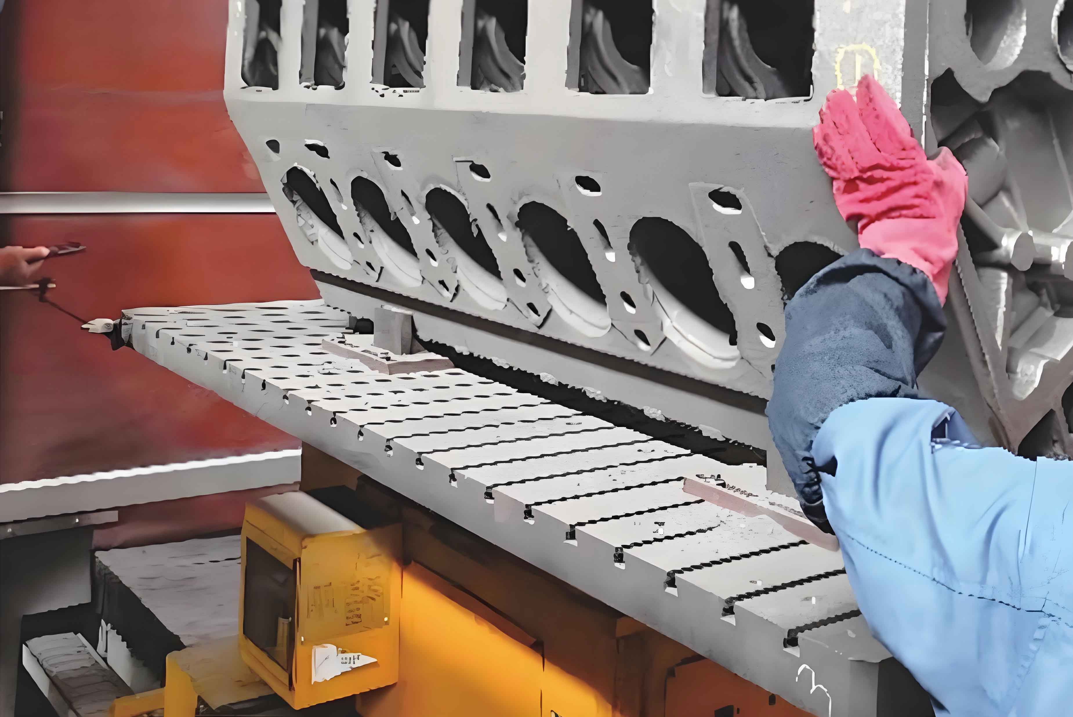
The engine cylinder block is the backbone of automotive engines, determining their performance, durability, and efficiency. As the automotive industry evolves, the machining processes for engine cylinder block holes must advance to meet stringent precision and quality demands. This study delves into the critical technologies and methodologies for machining engine cylinder block holes, proposes optimization strategies, and validates their effectiveness through practical case analyses.

1. Machining Workflow of Engine Cylinder Blocks
The manufacturing of engine cylinder blocks involves sequential stages to ensure dimensional accuracy and surface integrity. Below is a summarized workflow:
1.1 Raw Material Preparation
High-strength alloy steel is selected for its wear resistance and thermal stability. The material undergoes cutting to form rough blanks.
1.2 Rough Machining
Primary shaping is performed using milling machines and lathes to remove excess material. Key parameters include:
| Process Parameter | Value/Description |
|---|---|
| Cutting Speed | 80–120 m/min |
| Feed Rate | 0.2–0.5 mm/rev |
| Depth of Cut | 2–5 mm |
1.3 Heat Treatment
Thermal processes like quenching and tempering enhance material hardness (HRC 45–50) and toughness. The relationship between hardness (HH) and tempering temperature (TT) is modeled as:H=H0−k⋅ln(T)H=H0−k⋅ln(T)
where H0H0 is initial hardness and kk is a material constant.
1.4 Semi-Finishing
High-precision tools refine features such as bolt holes and threads. Surface roughness (RaRa) is reduced to ≤1.6 µm.
1.5 Finishing
CNC machines and grinding tools achieve micron-level tolerances. For cylindrical holes, the roundness error (ErEr) must satisfy:Er≤0.005 mmEr≤0.005mm
2. Hole Machining Processes
2.1 Rough Boring
Rapid material removal establishes the hole’s basic geometry. Critical factors include:
- Tool Selection: Carbide inserts with high wear resistance.
- Cooling: Emulsion-based fluids to dissipate heat (QQ) generated during cutting:
Q=Fc⋅vQ=Fc⋅v
where FcFc is cutting force and vv is cutting speed.
2.2 Semi-Finish Boring
Intermediate machining reduces surface roughness and refines dimensions. A comparative analysis of parameters:
| Parameter | Rough Boring | Semi-Finish Boring |
|---|---|---|
| Cutting Speed | 80 m/min | 120 m/min |
| Feed Rate | 0.2 mm/rev | 0.1 mm/rev |
| RaRa | 3.2 µm | 1.6 µm |
2.3 Finish Boring and Honing
Ultra-precision tools and honing machines achieve Ra≤0.4 μmRa≤0.4μm. The honing angle (θθ) optimizes surface texture:θ=arctan(vfvr)θ=arctan(vrvf)
where vfvf is feed velocity and vrvr is rotational velocity.
3. Common Challenges in Engine Cylinder Block Hole Machining
3.1 Dimensional Inaccuracy
Tool wear and thermal deformation cause deviations. For a hole diameter DD, the tolerance (ΔDΔD) must satisfy:ΔD≤±0.01 mmΔD≤±0.01mm
3.2 Shape Irregularities
Vibrations and uneven cutting forces induce ovality. The ovality error (EoEo) is calculated as:Eo=Dmax−Dmin2Eo=2Dmax−Dmin
3.3 Surface Defects
Micro-cracks and burrs degrade sealing performance. Post-machining polishing reduces RaRa by 30–50%.
4. Optimization Strategies for Engine Cylinder Block Hole Machining
4.1 Process Simplification
Combining rough, semi-finish, and finish boring into a single step using composite tools reduces cycle time by 30%.
4.2 Cutting Parameter Optimization
Adaptive control systems dynamically adjust parameters. For example, variable feed rate (ff) minimizes tool wear:f=f0⋅e−ktf=f0⋅e−kt
where f0f0 is initial feed rate and kk is a wear coefficient.
4.3 Machine Tool Upgrades
High-rigidity CNC machines improve stability. A case study showed:
| Metric | Before Optimization | After Optimization |
|---|---|---|
| Diameter Tolerance | ±0.01 mm | ±0.005 mm |
| RaRa | 0.8 µm | 0.4 µm |
| Cycle Time | 120 min | 80 min |
5. Conclusion
This study demonstrates that optimizing the machining processes for engine cylinder block holes significantly enhances precision, surface quality, and efficiency. By integrating advanced tools, adaptive parameter control, and machine upgrades, manufacturers can meet the evolving demands of the automotive industry while reducing costs. Future work will explore AI-driven real-time monitoring to further refine these processes.
Tables and Formulas Summary
Table 1: Comparison of Rough vs. Semi-Finish Boring Parameters
| Parameter | Rough Boring | Semi-Finish Boring |
|---|---|---|
| Cutting Speed | 80 m/min | 120 m/min |
| Feed Rate | 0.2 mm/rev | 0.1 mm/rev |
| RaRa | 3.2 µm | 1.6 µm |
Formula 1: Heat Generation During CuttingQ=Fc⋅vQ=Fc⋅v
Formula 2: Honing Angle Optimizationθ=arctan(vfvr)θ=arctan(vrvf)
Formula 3: Adaptive Feed Rate Adjustmentf=f0⋅e−ktf=f0⋅e−kt
