
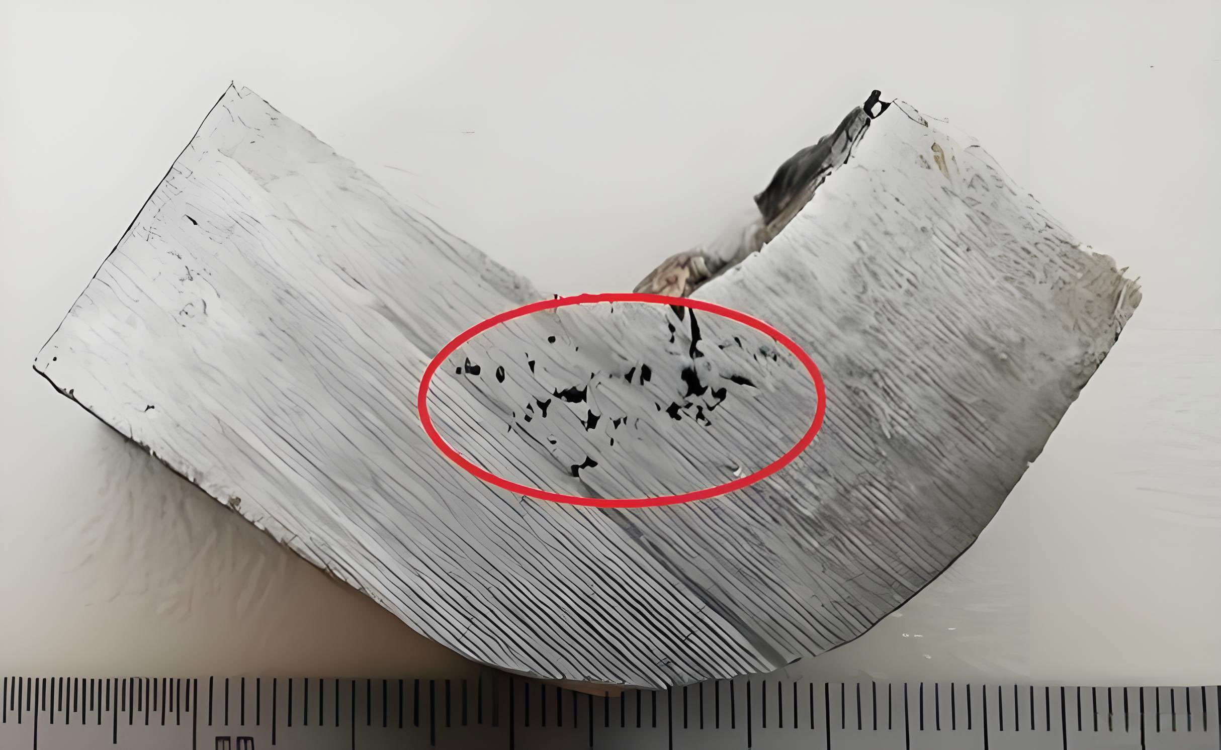
The manufacturing of high-quality rolls is fundamental to the steel industry, as rolls are critical consumable components in rolling mills. Their performance directly impacts product quality, production efficiency, and operational costs. Among various manufacturing techniques, centrifugal composite casting is widely employed to produce rolls with a hard, wear-resistant outer layer and a tough, ductile core. However, a persistent challenge in this process, particularly for high-chromium cast iron rolls used in finish rolling, is the formation of shrinkage in casting defects—specifically, shrinkage porosity and cavities within the roll body. These defects lead to ultrasonic testing failures, such as bottom wave attenuation exceeding allowable limits (e.g., >10% of full-screen amplitude), resulting in high scrap rates and significant economic losses. This research systematically investigates the root causes and influencing factors of shrinkage in casting in roll bodies, utilizing numerical simulation, experimental validation, and process optimization to develop effective mitigation strategies.
1. Introduction and Research Background
As a global leader in steel production, China’s industry continuously demands higher performance and quality from its production equipment. Rolls, constituting 5% to 15% of rolling mill operating costs, are at the forefront of this demand. The centrifugal composite casting process involves sequentially casting the outer and intermediate layers via horizontal centrifugal casting, followed by gravity casting of the core. While this method yields a dense outer structure, controlling internal quality, especially preventing shrinkage in casting in the thick roll body section, remains technically challenging. Traditional methods relying on experience and trial-and-error are inefficient and costly. Therefore, employing numerical simulation technology to analyze the filling, solidification, and defect formation mechanisms provides a powerful, scientific approach to optimize the process. This study aims to establish a reliable numerical model, identify key process parameters influencing shrinkage, and propose practical solutions to enhance product yield and quality.
2. Theoretical Foundations and Numerical Modeling
The centrifugal composite casting process is a complex transient phenomenon involving fluid flow, heat transfer, and phase change. Accurate numerical simulation relies on fundamental mathematical models governing these physics.
2.1 Governing Equations for Filling and Solidification
The filling process of molten metal is modeled as a transient, viscous, incompressible flow, adhering to the conservation laws of mass, momentum, and energy.
Mass Conservation (Continuity Equation):
$$
\frac{\partial \rho}{\partial t} + \nabla \cdot (\rho \vec{v}) = 0
$$
For incompressible flow, density $\rho$ is constant, simplifying to:
$$
\nabla \cdot \vec{v} = 0
$$
Momentum Conservation (Navier-Stokes Equations):
$$
\rho \left( \frac{\partial \vec{v}}{\partial t} + (\vec{v} \cdot \nabla) \vec{v} \right) = -\nabla p + \mu \nabla^2 \vec{v} + \rho \vec{g}
$$
Energy Conservation Equation:
$$
\rho c_p \left( \frac{\partial T}{\partial t} + \vec{v} \cdot \nabla T \right) = \nabla \cdot (k \nabla T) + S_T
$$
Where $\vec{v}$ is velocity, $p$ is pressure, $\mu$ is dynamic viscosity, $\vec{g}$ is gravity, $T$ is temperature, $c_p$ is specific heat, $k$ is thermal conductivity, and $S_T$ is a source term (e.g., latent heat).
The solidification process focuses on heat transfer, with the latent heat $L$ released during phase change handled by the enthalpy method:
$$
H = \int_{T_{ref}}^T c_p \, dT + (1 – f_s) L
$$
$$
\rho \frac{\partial H}{\partial t} = \nabla \cdot (k \nabla T)
$$
where $H$ is enthalpy and $f_s$ is the solid fraction.
2.2 Prediction of Shrinkage in Casting
Shrinkage in casting defects form due to inadequate liquid metal feeding during the final stages of solidification. The Niyama criterion is a widely used index for predicting shrinkage porosity, defined as:
$$
Ny = \frac{G}{\sqrt{\dot{T}}}
$$
where $G$ is the temperature gradient and $\dot{T}$ is the cooling rate at the solidus temperature. Regions with a Niyama value below a critical threshold are prone to shrinkage in casting. In this study, the porosity module within the simulation software, which often incorporates such feeding criteria, is used to identify potential defect locations.
3. Numerical Simulation Setup and Methodology
A full-scale 3D model of the roll and its mold assembly (including chill mold, sand cores, pouring basin, etc.) was created. The mesh was carefully generated with refined elements in critical areas like the coating layer.
Material Properties and Boundary Conditions: The chemical compositions of the outer layer, intermediate layer, and core materials are detailed in Table 1. Their temperature-dependent thermophysical properties were calculated by the simulation software. Key interfacial heat transfer coefficients (HTC) were assigned based on material pairs, as shown in Table 2.
| Layer | C | Si | Mn | Cr | Ni | Mo |
|---|---|---|---|---|---|---|
| Outer | 2.6 | 0.45 | 0.85 | 17.7 | 1.25 | 1.25 |
| Intermediate | 3.3 | 2.3 | 0.4 | ≤0.25 | 0.4/0.8 | 0 |
| Core | 1.3 | 2.2 | 0.4 | ≤0.1 | ≤0.1 | ≤0.1 |
Table 1: Chemical composition of roll materials (wt.%).
| Interface | HTC (W/m²·K) |
|---|---|
| Roll Metal / Chill Mold | 3000 – 4000 |
| Metal / Sand Mold | 300 – 1000 |
| Sand / Sand | 200 – 300 |
Table 2: Assigned interfacial heat transfer coefficients.
The three-stage casting process was simulated sequentially using a “physical file transfer” method. The temperature field at the end of the outer layer casting was used as the initial condition for the intermediate layer simulation. Similarly, the final state of the intermediate layer casting provided the initial mold temperature for the core gravity casting simulation. Process parameters are listed in Table 3.
| Process Stage | Pouring Temp. (°C) | Pouring Time (s) | Mold Temp. (°C) | Rotation Speed (rpm) |
|---|---|---|---|---|
| Outer Layer Casting | 1425 | 80 | 130 | 870 |
| Intermediate Layer Casting | 1525 | 60 | – | 870 |
| Core Gravity Casting | 1350 | 180 | 130 | – |
Table 3: Key process parameters for simulation.
4. Analysis of Process Parameters on Shrinkage in Casting
The simulation results revealed a characteristic “hourglass-shaped” temperature field in the roll body during solidification, where the upper and lower sections of the body solidified before the central region. This isolated the central liquid pool, preventing effective feeding from the riser and leading to shrinkage in casting. Key points (A: top riser, B: upper body, C: mid-body, D: lower body, E: bottom neck) were monitored to quantify this behavior.
4.1 Effect of Pouring Temperature
The core pouring temperature was varied from 1350°C to 1410°C. The time difference between the solidification of Point B (upper body) and Point C (mid-body), denoted as $\Delta \tau$, was found to be critical. A higher pouring temperature delayed solidification overall but reduced the $\Delta \tau$ between B and C, slightly improving feeding. The volume of predicted shrinkage in casting decreased with increasing pouring temperature.
| Pouring Temp. (°C) | $\Delta \tau_{B-C}$ (s) | Shrinkage Volume (cc) |
|---|---|---|
| 1350 | 800 | 155 |
| 1370 | 700 | 150 |
| 1390 | 600 | 145 |
| 1410 | 500 | 140 |
Table 4: Effect of pouring temperature on solidification timing and shrinkage.
A relationship was derived where the shrinkage volume $V$ relates to the time difference:
$$
V = V_w – (\Delta \tau_w – \Delta \tau_{jw}) \times f + N_{jw}
$$
where $V_w$ and $\Delta \tau_w$ are reference values, $\Delta \tau_{jw}$ is the time difference at a specific temperature, $f$ is a constant (0.05 for pouring temperature), and $N_{jw}$ is a correction factor.
4.2 Effect of Riser Height
The height of the top riser was varied (1.5m, 2.0m, 2.5m). An optimal riser height of 2.0m was identified, which minimized the $\Delta \tau_{B-C}$ and consequently the shrinkage in casting volume. Taller risers increased metallostatic pressure but also increased heat loss from the riser wall, leading to sub-optimal solidification patterns.
| Riser Height (m) | $\Delta \tau_{B-C}$ (s) | Shrinkage Volume (cc) |
|---|---|---|
| 1.5 | 800 | 155 |
| 2.0 | 430 | 95 |
| 2.5 | 500 | 105 |
Table 5: Effect of riser height on solidification timing and shrinkage.
The relationship for riser height follows a similar form, with constant $f = 0.154$:
$$
V = V_m – (\Delta \tau_m – \Delta \tau_{mk}) \times f + N_{mk}
$$
5. Process Optimization, Validation, and Proposed Solutions
5.1 Experimental Validation
To validate the numerical model, temperature measurements were taken on the outer surface of the chill mold during actual production runs. The comparison between simulated and measured temperatures at a mid-point (M) on the mold showed good agreement in trend and magnitude, with a maximum error of 4.9% during centrifugal casting and 4.3% during gravity casting cooling. This confirmed the accuracy of the model’s thermal predictions.
5.2 Optimized Process: Interrupted Pouring
An interrupted pouring technique was proposed and simulated. This involves pouring the bottom neck and roll body core first, waiting for a specified interval (5, 10, 15 minutes), and then pouring the top riser. This allows the body section to cool and contract slightly, creating a more favorable temperature gradient for subsequent feeding from the hot riser metal. The interval of 15 minutes yielded the best reduction in shrinkage in casting.
| Interval (min) | $\Delta \tau_{B-C}$ (s) | Shrinkage Volume (cc) |
|---|---|---|
| 5 | 400 | 78 |
| 10 | 320 | 68 |
| 15 | 280 | 58 |
Table 6: Effect of interrupted pouring interval on shrinkage.
The governing relationship uses constant $f = 0.2$:
$$
V = V_j – (\Delta \tau_j – \Delta \tau_{jg}) \times f + N_{jg}
$$
5.3 Proposed Design Modification: Insulating Sleeve
A key finding was the premature solidification of the roll body’s upper region. To address this, a tapered insulating sleeve placed on the upper outer periphery of the chill mold was conceptually designed and simulated. Its purpose is to retard cooling in the upper body, promoting sequential solidification from the bottom upwards.
Effect of Sleeve Taper Angle: With a fixed wall thickness of 50mm, the taper angle was varied. A taper of 10.2° provided the most uniform feeding channel and the minimum shrinkage in casting volume.
| Taper Angle (°) | $\Delta \tau_{B-C}$ (s) | Shrinkage Volume (cc) |
|---|---|---|
| 2.2 | 200 | 62 |
| 6.2 | 150 | 57 |
| 10.2 | 100 | 52 |
| 14.3 | 290 | 64 |
Table 7: Effect of insulating sleeve taper angle on shrinkage (50mm wall).
The relationship is given with $f = 0.25$:
$$
V = V_z – (\Delta \tau_z – \Delta \tau_{zd}) \times f + N_{zd}
$$
Effect of Sleeve Wall Thickness: With a fixed taper of 10.2°, increasing wall thickness from 50mm to 250mm was counterproductive, as it increased $\Delta \tau_{B-C}$ and shrinkage volume, indicating excessive insulation altered the gradient unfavorably.
| Wall Thickness (mm) | $\Delta \tau_{B-C}$ (s) | Shrinkage Volume (cc) |
|---|---|---|
| 50 | 100 | 52 |
| 150 | 200 | 60 |
| 250 | 300 | 68 |
Table 8: Effect of insulating sleeve wall thickness on shrinkage (10.2° taper).
$$
V = V_h – (\Delta \tau_h – \Delta \tau_{bh}) \times f + N_{bh}
$$
with $f = 0.04$.
6. Conclusions
This research successfully applied numerical simulation to diagnose and mitigate shrinkage in casting defects in centrifugal composite cast rolls. The primary cause was identified as the “hourglass-shaped” temperature field leading to premature solidification of the upper roll body, isolating the mid-section. The time difference $\Delta \tau_{B-C}$ between the solidification of the upper and mid-body was established as a key indicator for shrinkage in casting severity.
- Process parameters like pouring temperature and riser height significantly influence $\Delta \tau_{B-C}$ and final shrinkage volume, with quantifiable relationships established.
- The interrupted pouring technique and the novel design of a tapered insulating sleeve (optimally at 10.2° taper, 50mm wall) were demonstrated through simulation to effectively reduce $\Delta \tau_{B-C}$ and shrink the volume of shrinkage in casting by over 50% compared to the baseline process.
- The constant $f$ in the derived predictive relationships reflects the sensitivity of shrinkage reduction to parameter changes; a larger $f$ value corresponds to a greater potential for defect reduction for a given improvement in $\Delta \tau_{B-C}$.
The study provides a validated model and practical optimization guidelines for foundries to improve the internal soundness of high-chromium cast iron rolls, thereby reducing ultrasonic testing rejections and enhancing production efficiency.