1. Introduction
The four – cylinder piston pump is a crucial component in various industrial systems, especially in hydraulic applications. Austenitic stainless steel is widely used in the manufacturing of piston pump castings due to its excellent properties such as high – temperature resistance, corrosion resistance, and good mechanical properties. However, the casting process of austenitic stainless steel four – cylinder piston pumps is complex, facing challenges like complex structures, strict dimensional accuracy requirements, and high – quality expectations. This paper aims to comprehensively explore the casting process of such pumps, covering process design, material selection, numerical simulation, and quality control.
1.1 Significance of the Research
The development of a reliable and efficient casting process for austenitic stainless steel four – cylinder piston pumps is of great significance. In industrial production, piston pumps are used in a wide range of applications, from hydraulic machinery in construction to precision control systems in the aerospace industry. The quality of the casting directly affects the performance, durability, and safety of the piston pump. By optimizing the casting process, we can improve product quality, reduce production costs, and enhance the competitiveness of products in the market.
1.2 Research Objectives
The main objectives of this research are as follows:
- To design an appropriate casting process for austenitic stainless steel four – cylinder piston pumps, including the selection of pouring position, pouring system, and the design of risers and chills.
- To use advanced numerical simulation technology to optimize the casting process, predict and prevent potential casting defects such as shrinkage porosity and cold shuts.
- To verify the effectiveness of the designed casting process through production trials and quality inspections, and to ensure that the final product meets the relevant standards and requirements.
2. Product Information and Technical Requirements
2.1 Product Overview
The four – cylinder piston pump studied in this paper has a complex structure, with multiple cavities and connection parts. The product’s basic information is shown in Table 1.
| Name | Material | Mass/kg | Outline Dimensions/mm | Maximum Wall Thickness/mm | Minimum Wall Thickness/mm |
|---|---|---|---|---|---|
| Four – Cylinder Piston Pump | ZG1Cr18Ni9Ti | 230 | 720×437×388 | 55 | 15 |
| Table 1: Product Basic Information |
2.2 Technical Requirements
- Dimensional Accuracy: The product’s dimensional accuracy needs to meet the CT11 level in GB/T 6414. This high – level accuracy requirement ensures the proper assembly and operation of the piston pump. Any deviation in dimensions may lead to problems such as leakage or abnormal wear during operation.
- Chemical Composition and Mechanical Properties: The material grade is ZG1Cr18Ni9Ti. Its chemical composition requirements are shown in Table 2, and mechanical properties requirements are shown in Table 3. These properties are essential for the pump to withstand high – pressure environments and harsh working conditions.
| Chemical Composition | Mn | Ti |
|---|---|---|
| Standard ≤ | 0 | 0.02 – 0.80 |
| Table 2: Chemical Composition Requirements (w/%) |
| Item | Tensile Strength/MPa | Yield Strength/MPa | Elongation/% | Section Shrinkage/% | Impact Energy (- 150℃)/J |
|---|---|---|---|---|---|
| Standard | ≥520 | ≥205 | ≥40 | ≥45 | ≥78 |
| Table 3: Mechanical Properties Requirements |
- Quality Inspection Standards: The casting should comply with the provisions of JB/T6880.2 “Cast Steel Parts for Pumps”. As a pressure – bearing part, the pump cavity needs to undergo a hydraulic pressure test with a test pressure of 5.3 MPa for 30 minutes without leakage. In addition, the casting must be pickled, passivated, and sand – blasted to ensure its surface quality and corrosion resistance.
3. Process Scheme
3.1 Difficulty Identification
Analyzing the structure of the casting and combining with the product acceptance standards, several difficulties are identified:
- Complex Structure and Processing: The product has a complex structure with numerous machining surfaces. In particular, the cylinder ports for installing pistons must be free of defects. Any defect in these areas can affect the sealing performance and operation of the piston pump.
- Internal Cavity Cleaning and Cold Iron Removal: The internal cavity of the casting is complex, making sand cleaning and cold iron removal difficult. Residual sand or cold iron in the cavity can cause blockages or abnormal wear in the pump during operation.
- Shrinkage Porosity Requirements: The casting needs to pass a 3.5 MPa pressure test, so the distribution of shrinkage porosity in the casting must be strictly controlled. Shrinkage porosity can reduce the strength of the casting and lead to leakage during the pressure test.
- Material – Specific Challenges: Austenitic stainless steel has a relatively large casting shrinkage rate. Lack of experience in selecting process shrinkage parameters for this material can result in problems such as misalignment of the cylinder port center and inconsistent shrinkage of the casting outline dimensions.
3.2 Scheme Planning
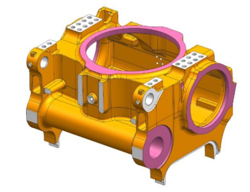
- Pouring Position Selection: The pouring position should be conducive to the sequential solidification of the main structure of the casting and facilitate the setting of risers for feeding. For this product, the cylinder ports are placed upward, which is beneficial for placing risers to feed the casting and also conducive to cavity exhaust. A schematic diagram of the pouring position is shown in Figure 1.
- Pouring System Selection: A bottom – pouring and open – type pouring system is chosen. The bottom – pouring method can ensure that the molten metal enters the mold cavity smoothly, reducing the risk of air entrapment and oxide inclusion. The open – type pouring system can balance the pouring pressure and prevent excessive flow velocity at the ingate.
- Manufacturing Technology: The 3DP sand – molding technology is adopted for production. This technology has the advantages of high flexibility, short production cycle, and the ability to produce complex – shaped castings. It eliminates the need for traditional molds, reducing mold – making costs and time. A flow chart of the 3DP sand – molding process is shown in Figure 2.
3.3 Casting Process Plan
- Pouring Position Determination: The pouring position is determined based on comprehensive considerations such as the structure, size, mass, technical requirements, casting alloy characteristics, and casting method of the casting. For the four – cylinder piston pump, placing the piston cylinder ports upward not only facilitates riser placement for feeding but also helps to ensure a good filling temperature field of the casting. Due to the relatively thin overall wall thickness of the casting, multiple ingates are required to ensure proper filling and prevent cold shuts. At the same time, considering the wall – thickness relationship, the ingates should be designed below the risers to prevent sand erosion.
- Pouring System Design: The design of the pouring system should meet the following requirements:
- Guide the molten metal to fill the mold cavity smoothly and continuously, avoiding excessive turbulence that may cause air entrapment, metal oxide inclusions, and sand – core erosion.
- Adopt a matrix – type pouring system to control the flow direction and speed during the filling process, ensuring a clear and complete casting outline.
- Fill the mold cavity within an appropriate time to avoid defects such as sand inclusion, cold shut, and scab.
- Regulate the temperature distribution in the mold to enhance casting feeding, reduce casting stress, and prevent casting deformation and cracking.
- Have slag – blocking and slag – overflow capabilities to purify the molten metal.
- The structure of the pouring system should be simple and reliable, reducing molten – metal consumption and facilitating cleaning.
- Considering the high pouring temperature and easy oxidation of cast steel, a bottom – pouring ladle is used, and an open – type pouring system is adopted to counteract the pouring pressure of the ladle and avoid excessive flow velocity at the ingate. A schematic diagram of the pouring system is shown in Figure 3.
Casting Numerical Simulation: First, a solidification simulation of the bare mold (without drawing the pouring system, risers, and chills) is carried out. By doing so, the hot – spot positions and the corresponding modulus sizes are found, and the preliminary distribution of shrinkage porosity is judged, as shown in Figure 4. Based on the results of the bare – mold simulation, risers and chills are set up accordingly. Then, through multiple adjustments and simulations, the optimal process plan is determined.
Riser and Chill Design: Through multiple adjustments and simulations, the final design plan for risers and chills is determined, as shown in Figure 5. Risers and chills are used in combination at the top cylinder ports and side flanges to eliminate shrinkage porosity. In addition, risers and chills are also used at other key positions to ensure that there is no shrinkage porosity in the critical areas of the casting. This plan ensures a stable filling of the molten metal, with no risk of turbulence and sand erosion, and meets the quality requirements.
Sand – Mold Process Plan: The 3DP sand – molding technology is not limited by the structure. Under the premise of ensuring overall strength and facilitating sand cleaning, the main core should carry out as much of the product structure as possible to reduce the number of sand molds. For this product, it is divided into 8 cores. Due to the difficulty of sand cleaning and cold – iron placement, the internal – cavity core is made separately. The sand mold is made in a conformal manner, with a sand – eating amount of 70 – 80 mm, and is cast in a buried – box method. A schematic diagram of the sand – mold structure is shown in Figure 6.
4. Melting Process Design
4.1 Material Characteristics
ZG1Cr18Ni9Ti is a typical 18 – 8 austenitic cast stainless steel. It has high toughness, plasticity, and excellent oxidation – resistance and corrosion – resistance properties. The presence of the stable chemical element titanium in the steel improves its intergranular corrosion resistance.
4.2 Control Key Points
- Raw Material Quality: Austenitic stainless steel castings are produced using an intermediate – frequency furnace. The quality of the raw materials added must be improved (free of rust and oil stains). Before adding, the raw materials must be baked to a certain temperature using natural gas.
- Ti Element Control: Pay attention to the Ti element content required in the material. Since Ti is extremely active and easily oxidized, the addition time of the Ti element needs to be carefully controlled, and the quality of the post – melting – steel – slag skimming should be ensured.
- Steel Ladle Treatment: The steel ladle should be baked for more than 40 minutes. After the molten steel is tapped into the ladle, the argon – blowing time and pressure should be controlled to ensure the cleanliness of the molten steel.
- Pouring Temperature: Considering that the main wall thickness of the casting is 15 mm and the internal cavity is complex, making sand cleaning difficult, the pouring temperature should be kept as low as possible on the premise of ensuring complete filling.
5. Heat Treatment Process Design
5.1 Heat Treatment Principle
Austenitic stainless steel is heat – treated by solution treatment. This treatment involves heating the steel to a certain temperature at which the excess phase is fully dissolved into the solid solution, maintaining this temperature for a certain period, and then rapidly cooling.
5.2 Heat Treatment Process Parameters
The detailed heat – treatment process parameters are shown in Table 4.
| Process | Loading Temperature/℃ | Heating Rate/℃ | Holding Temperature/℃ | Holding Time/h | Unloading Temperature/℃ | Cooling Method |
|---|---|---|---|---|---|---|
| Solution Treatment | ≤200 | ≤200 | 980 ± 5 or 1060 ± 5 | 1 or 2 | ≥910 ± 5 | Water – Cooling |
| Table 4: Heat – Treatment Process Parameters |
6. Production Verification and Inspection
6.1 Production Trial
According to the above – designed process plan, production trials are carried out. The first – produced part is subjected to various tests in accordance with the technical requirements.
6.2 Inspection Items
- Dimensional Inspection: A measuring arm is used to perform three – dimensional dimensional measurement and fitting comparison on the casting. The dimensional accuracy of the casting meets the requirements of CT11 level in GB/T 6414 – 2017. The dimensional inspection report is shown in Figure 8.
- Mechanical Property Inspection: The mechanical properties of single – cast test blocks are tested, and all results meet the acceptance standard requirements. The mechanical property test results are shown in Table 5.
| Test Item | Measured Value |
|---|---|
| Tensile Strength/MPa | 640 |
| Yield Strength/MPa | 250 |
| Elongation/% | 48 |
| Section Shrinkage/% | 47.5 |
| Impact Energy (- 150℃)/J | 127 |
| Table 5: Mechanical Property Test Results |
- Defect Inspection: PT/UT inspection is carried out on the key parts of the casting, and no shrinkage porosity and other defects are found, which meets the quality requirements.
7. Results and Discussion
7.1 Process Optimization Results
The combination of 3DP sand – molding technology and traditional casting methods has significantly shortened the research and development and trial – production cycle of new products. It can achieve delivery in 15 – 20 days, which is at least 70% shorter than the traditional casting research and development cycle. This is mainly due to the high flexibility of 3DP technology, which can quickly produce sand molds without the need for time – consuming mold – making processes.
7.2 Product Quality Improvement
The use of sand – mold 3D printing technology is not limited by the structure. By making the internal – cavity core and the upper – layer sand core as a whole for printing and coating, the number of sand cores is reduced, and the difficulty of core assembly and mold closing is also reduced. This effectively controls the dimensional accuracy of the casting. In addition, through the optimization of the casting process, including the design of risers, chills, and the pouring system, as well as the use of numerical simulation technology, the internal quality of the casting is improved, and the occurrence of defects such as shrinkage porosity is effectively prevented.
7.3 Challenges and Future Research Directions
Although the current casting process has achieved good results, there are still some challenges. For example, the cost of 3DP sand – molding technology is relatively high, which may limit its large – scale application in some cost – sensitive industries. In the future, research can be focused on reducing the cost of 3DP technology, such as exploring more cost – effective printing materials and improving printing efficiency. In addition, further research can be carried out on the heat – treatment process of austenitic stainless steel to optimize the mechanical properties of the casting more precisely.
8. Conclusion
This paper has comprehensively studied the casting process of austenitic stainless steel four – cylinder piston pumps. Through the design of the casting process, including the selection of pouring position, pouring system, riser and chill design, sand – mold design, as well as the optimization of melting and heat – treatment processes, and production verification and inspection, a reliable casting process has been developed. The combination of 3DP sand – molding technology and traditional casting methods has shortened the production cycle, improved product quality, and met the acceptance standards. However, continuous research and improvement are still needed to address existing challenges and further enhance the performance and competitiveness of austenitic stainless steel four – cylinder piston pump castings.