
In my extensive research on the welding repair of white cast iron rolling mill rolls, I have delved into the critical issues surrounding the premature failure of these essential components in steel production. White cast iron, known for its high hardness and wear resistance, is widely used as the surface layer of chilled and indefinite chilled cast iron rolls due to its cost-effectiveness. However, its inherent brittleness and high shrinkage rate often lead to local defects such as spalling, cracking, and even fracture during casting and service, resulting in significant economic losses. The annual financial impact from scrapped white cast iron rolls is substantial, highlighting the urgent need for effective repair techniques. My work focuses on demonstrating that white cast iron, despite its reputation for being unweldable, can be successfully repaired through specialized welding materials and processes, thereby extending roll life and reducing costs.
The mechanism behind the spalling of white cast iron roll surfaces is primarily attributed to thermal fatigue caused by cyclic thermal stresses. During rolling operations, the roll surface is subjected to repeated heating from hot steel billets (at temperatures ranging from 800°C to 1200°C) and rapid cooling from water jets, creating significant temperature gradients. This leads to alternating compressive and tensile stresses in the thin surface layer. I have analyzed that the thermal stress (\(\sigma_t\)) can be approximated by the formula:
$$ \sigma_t = E \cdot \alpha \cdot \Delta T $$
where \(E\) is the modulus of elasticity, \(\alpha\) is the coefficient of thermal expansion, and \(\Delta T\) is the temperature change. For white cast iron, with its low ductility (impact toughness as low as 2-5 J/cm²) and high hardness (50-65 HRC), these stresses induce microcracks that propagate into network cracks, eventually causing particle or flake spalling. The presence of inclusions or casting defects exacerbates this process. Understanding this failure mode is crucial for developing welding repair strategies that address the root causes.
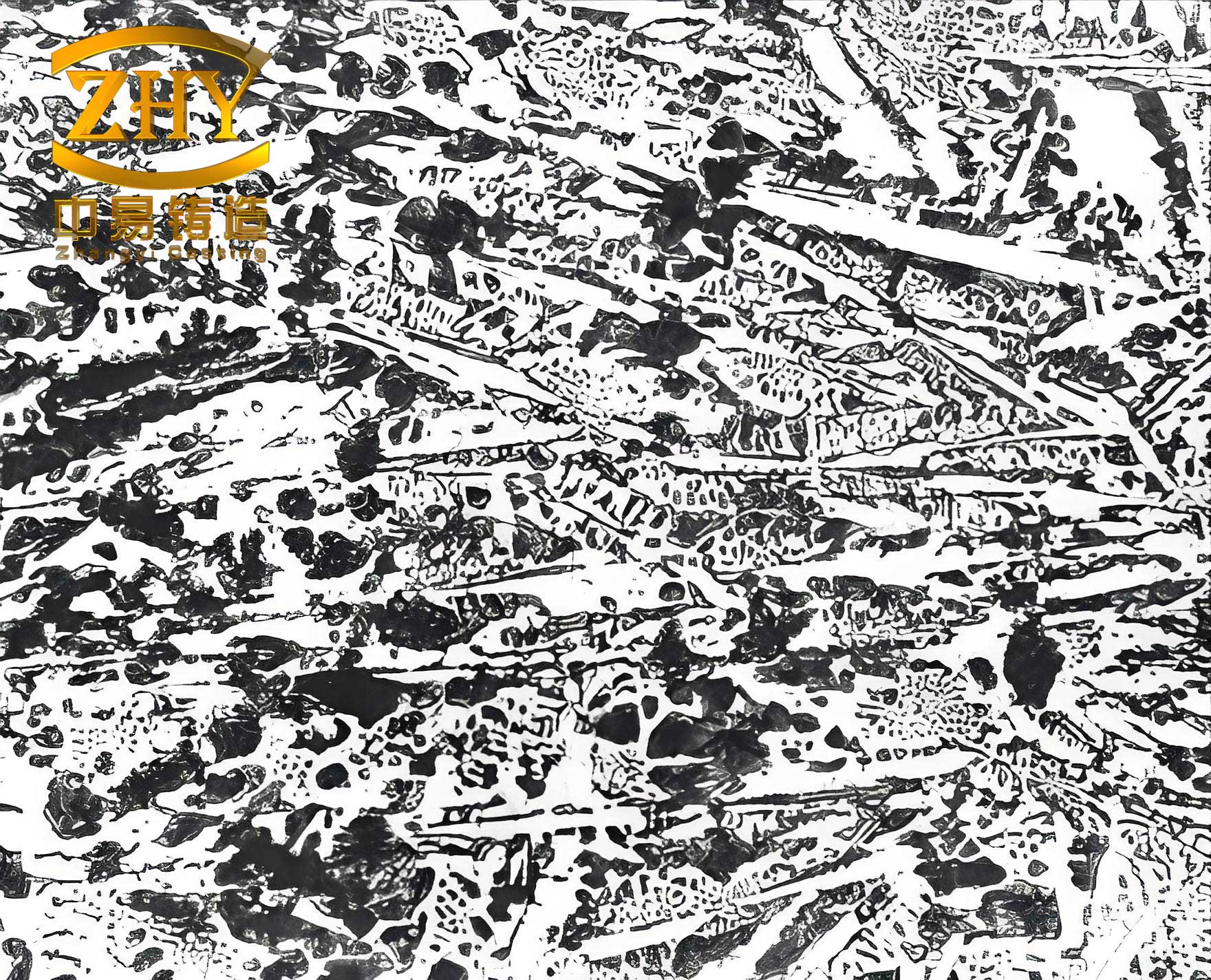
The weldability of white cast iron is notoriously poor due to its microstructure, which consists of continuous cementite networks with ledeburite and pearlite, as shown in the image above. This structure results in high hardness but minimal plasticity, making it susceptible to cracking under welding thermal stresses. Conventional welding approaches often fail because the rapid cooling during welding (with cooling rates of 50-100°C/s) generates severe temperature gradients and residual stresses. In my analysis, I have considered the challenges: white cast iron cannot absorb the expansion and contraction stresses during welding, leading to inevitable cracks in the heat-affected zone. Historical literature, such as the American Welding Handbook, categorizes white cast iron as unweldable under normal conditions, but my research aims to overturn this notion by introducing tailored solutions.
To overcome these challenges, I developed two special welding electrodes, designated as Electrode A (for the buffer layer) and Electrode B (for the working layer). These electrodes are designed with specific metallurgical characteristics to ensure compatibility with white cast iron. The composition and properties are summarized in the tables below.
| Element | C | Si | Mn | P | S | Cr | Ni | Mo |
|---|---|---|---|---|---|---|---|---|
| Content | 3.0-3.5 | 0.4-0.8 | 0.2-0.6 | <0.3 | <0.15 | 0.2-0.6 | 0-0.5 | 0-0.3 |
This composition yields a surface hardness of 50-65 HRC, but the brittleness necessitates careful welding material selection. My electrodes are formulated to address four key technical aspects: spheroidization of carbides in the fusion zone, matching thermal expansion coefficients, achieving comparable wear resistance, and ensuring good fusion compatibility.
| Electrode | Coating Type | Core Wire | Key Alloying Elements | Deposited Metal Microstructure | Hardness (HRC) |
|---|---|---|---|---|---|
| Electrode A (Buffer) | Graphite-type with Ba and REM | Low-carbon alloy steel | Ni, Mo, spheroidizers | Austenite with spheroidal graphite | 20-30 |
| Electrode B (Working) | Basic low-hydrogen | Medium-carbon steel | Cr, Ni, W, V, carbide formers | Martensite, carbides, retained austenite | 50-60 |
Electrode A produces a high-plasticity buffer layer with spheroidal graphite, which enhances crack resistance and allows for effective stress relief through peening. The spheroidal graphite, compared to flake graphite, reduces stress concentrations and improves ductility. The microstructure is characterized by pure austenite and spherical graphite particles, as described by the phase transformation equation during cooling:
$$ \gamma \rightarrow \alpha + G_{spherical} $$
where \(\gamma\) is austenite, \(\alpha\) is ferrite, and \(G_{spherical}\) is spheroidal graphite. This structure minimizes shrinkage stresses during welding. Electrode B, on the other hand, forms a wear-resistant working layer with a complex alloy system of Cr-Ni-W-V. The hardness is tailored to match white cast iron, and the microstructure includes martensite, carbide particles, and 10-20% retained austenite to balance toughness. The formation of carbides can be expressed as:
$$ M + C \rightarrow M_xC_y $$
where M represents carbide-forming elements like Cr, W, and V. This enhances wear resistance while maintaining adequate fracture resistance.
The first technical key is the spheroidization of carbides in the fusion zone. Without treatment, the fusion zone between the weld and white cast iron exhibits continuous network cementite (Fe$_3$C), which is highly brittle and prone to cracking. I incorporated modifiers such as potassium and sodium into the electrode coatings to promote carbide spheroidization. This transforms the harmful network into isolated spheroidal carbides, significantly improving the toughness of the fusion zone. The process can be modeled using diffusion-controlled growth:
$$ r(t) = \sqrt{D \cdot t} $$
where \(r(t)\) is the carbide radius, \(D\) is the diffusion coefficient, and \(t\) is time. Spheroidization reduces stress concentration factors, enhancing the bond strength. In tests, fractures occurred in the parent white cast iron rather than the fusion zone, confirming the effectiveness of this approach.
The second key is matching the coefficient of thermal expansion (CTE) between the weld metal and white cast iron. During rolling, the roll surface undergoes cyclic temperature fluctuations from 100°C to 500°C, causing thermal strains. If the CTE mismatch is large, interfacial stresses can lead to spalling. I measured the CTE of white cast iron and various weld metals using a dilatometer with an accuracy of ±0.1 µm/m·°C. The absolute elongation \(\Delta L\) as a function of temperature \(T\) is given by:
$$ \Delta L = L_0 \cdot \alpha \cdot (T – T_0) $$
where \(L_0\) is initial length and \(T_0\) is reference temperature. For white cast iron, \(\alpha\) ranges from 10-12 × 10$^{-6}$ /°C in the 20-500°C range. Electrode A’s deposit, with controlled graphite content and austenitic structure, achieves a CTE of 11-13 × 10$^{-6}$ /°C, while Electrode B’s deposit, through alloying with Ni and Cr, maintains 10-12 × 10$^{-6}$ /°C. This close match minimizes thermal stresses during service, as illustrated in the comparison below.
| Material | CTE | Notes |
|---|---|---|
| White Cast Iron | 10-12 | Base material |
| Electrode A Deposit | 11-13 | High graphite, austenite |
| Electrode B Deposit | 10-12 | Martensite with retained austenite |
| High Manganese Steel | 18-20 | Poor match, rejected |
The third key is achieving wear resistance comparable to white cast iron. The weld must withstand abrasive and adhesive wear during rolling without causing dimensional inaccuracies in steel plates. I conducted wear tests using a pin-on-disc machine under conditions simulating rolling: load 50 N, speed 0.5 m/s, temperature up to 300°C. The wear rate \(W\) is calculated as:
$$ W = \frac{\Delta m}{\rho \cdot A \cdot d} $$
where \(\Delta m\) is mass loss, \(\rho\) is density, \(A\) is area, and \(d\) is sliding distance. Results showed that Electrode B’s deposit, with optimized carbon (0.5-0.8 wt.%) and alloy content (Cr 4-6%, Ni 2-4%, W 1-2%, V 0.5-1%), achieved wear rates of 0.05-0.10 mm³/N·m, similar to white cast iron’s 0.08-0.12 mm³/N·m. Carbon content critically influences hardness, as shown in the empirical relationship:
$$ \text{Hardness (HRC)} = 20 + 15 \cdot [C] + 5 \cdot [Cr] – 2 \cdot [Ni] $$
where [C], [Cr], [Ni] are weight percentages. Excessive carbon (>1.0%) leads to brittle cementite networks, while low carbon (<0.3%) results in insufficient hardness. The balance ensures both wear resistance and crack resistance.
The fourth key is ensuring good fusion compatibility between the weld and white cast iron. Poor wetting or mixing can cause lack of fusion defects. I found that the Ni-to-C ratio in Electrode A’s deposit is crucial: a Ni/C ratio of 3-5 promotes excellent wetting and uniform mixing with molten white cast iron. The interfacial energy \(\gamma_{sl}\) between solid white cast iron and liquid weld metal is reduced by Ni additions, as described by:
$$ \gamma_{sl} = \gamma_s + \gamma_l – 2\sqrt{\gamma_s \gamma_l} \cdot \cos \theta $$
where \(\gamma_s\) and \(\gamma_l\) are surface energies, and \(\theta\) is contact angle. Lower \(\gamma_{sl}\) improves spreading. Graphite content in the weld must be controlled; too much graphite hinders fusion. Electrode A’s deposit, with 2-4% graphite in spheroidal form, achieves optimal fusion without defects.
In terms of welding process, I employed a cold welding technique without preheating, due to the large size of rolls (weighing up to 10 tons). The procedure involves: cleaning the defect, depositing Electrode A as a buffer layer with low heat input (current 90-120 A, voltage 22-26 V), peening each pass to relieve stresses, then overlaying with Electrode B for the working layer. The interpass temperature is kept below 100°C to minimize thermal stress. The heat input \(Q\) is calculated as:
$$ Q = \frac{\eta \cdot V \cdot I}{v} $$
where \(\eta\) is efficiency (0.8), \(V\) is voltage, \(I\) is current, and \(v\) is travel speed. Maintaining \(Q\) below 1.5 kJ/mm prevents excessive dilution and cracking.
Field trials on over 100 rolls in industrial settings demonstrated the success of this approach. The repaired rolls, with spalling defects as large as 200 mm × 200 mm × 20 mm, achieved continuous rolling of medium plates for over 10,000 tons, meeting production requirements. Some rolls even reached 15,000 tons without failure. Data from these trials are summarized below.
| Roll ID | Defect Size (mm) | Welding Electrodes Used | Rolling Tonnage (tons) | Result |
|---|---|---|---|---|
| R-01 | 150 × 150 × 15 | A + B | 12,500 | No spalling, worn evenly |
| R-02 | 200 × 200 × 20 | A + B | 10,800 | Minor wear, fusion zone intact |
| R-03 | 100 × 100 × 10 | A + B | 15,200 | Excellent performance |
| R-04 | 180 × 180 × 18 | A + B | 11,300 | No cracks detected |
The welded joints exhibited no detachment or spalling during service, indicating strong bonding. Microhardness profiles across the weld showed a gradual transition from the white cast iron substrate (600-700 HV) to the buffer layer (200-300 HV) and working layer (500-600 HV), minimizing stress concentrations. Impact toughness tests on the weld metal gave values of 30-50 J/cm² for Electrode A and 15-25 J/cm² for Electrode B, sufficient to absorb operational stresses.
In conclusion, my research proves that white cast iron is indeed weldable with the right materials and techniques. The two special electrodes, designed around four technical keys—carbide spheroidization, CTE matching, wear resistance optimization, and fusion compatibility—enable successful repair of white cast iron rolling mill rolls. This not only has substantial economic benefits by reducing scrap but also advances welding metallurgy for brittle materials. Future work could explore automation of the process or adaptation to other white cast iron components. The integration of these findings into industrial practice marks a significant step forward in maintaining critical infrastructure in steel manufacturing.
Throughout this study, the term “white cast iron” has been emphasized to underscore the material’s unique challenges and solutions. From failure analysis to electrode development, every aspect revolves around understanding and overcoming the limitations of white cast iron. The tables and formulas provided here summarize the core insights, offering a reproducible framework for welding professionals. As I reflect on this journey, it is clear that with innovation, even materials deemed unweldable can be reclaimed, extending their service life and contributing to sustainable industrial practices.