
In the manufacturing of critical engine components, the presence of casting defects is not merely an issue of quality control but a fundamental challenge to the structural integrity and functional reliability of the final product. This was starkly evident in the production of a main bearing cap for a Baudouin M26/M33 series diesel engine. The component, specified in ductile iron QT500-7, serves as a crucial structural element supporting the cranchshaft and must withstand significant cyclic and impact loads. Consequently, the casting mandates a complete absence of surface flaws like cracks, inclusions, or weld repairs, and internal discontinuities such as shrinkage porosity or cavities that could compromise its strength. The initial production process, utilizing a horizontally parted green sand mold with four castings per mold, was plagued by persistent and unacceptable casting defects, necessitating a fundamental redesign of the foundry methodology.
The original process configuration featured a gating system leading into the bolt boss areas, with shared conventional and insulated risers between pairs of castings. Chills were employed in three locations: a ring-shaped chill under the bearing saddle, a semi-circular chill on the cope-side inner bearing surface, and a smaller chill at the end of the cap. Despite this seemingly comprehensive setup, post-machining inspection revealed severe issues. The bolt hole regions exhibited subsurface shrinkage porosity, leading to crushing during bolt tightening. Furthermore, the finished bore surface showed unacceptable machining quality linked to surface irregularities. The root causes of these casting defects were multifaceted. The placement of gates and riser necks at the bolt bosses created localized hot spots, delaying solidification and reducing local hardness and strength. The chill on the bore surface caused excessive and uneven chilling, disrupting the machinability. Most critically, the casting’s inherent geometry, featuring a central recess, created two distinct thermal centers that were difficult to feed effectively under the original gating and risering scheme, leading to internal shrinkage porosity.
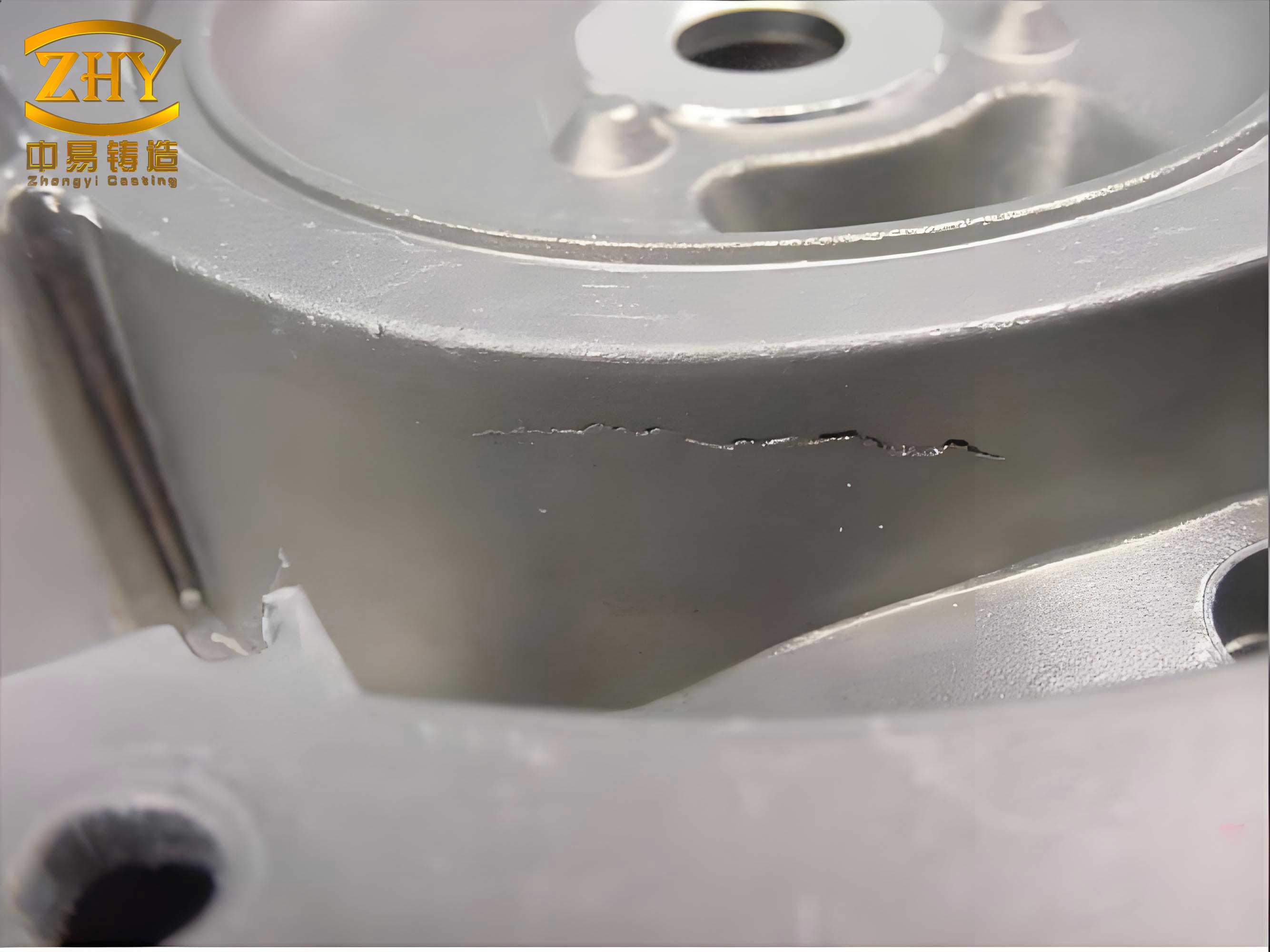
The fundamental metallurgical challenge with ductile iron is its mushy solidification behavior. Unlike alloys with a pronounced pasty zone, the solidification front is ill-defined, making feeding over long distances ineffective. Isolated liquid pools, or hot spots, form in sections with high thermal modulus (Volume/Surface Area ratio). If these pools cannot be fed by residual liquid from risers, they collapse to form shrinkage porosity, a primary category of internal casting defects. The solidification time for a section can be approximated by Chvorinov’s rule:
$$t = B \left( \frac{V}{A} \right)^n$$
where \( t \) is solidification time, \( V \) is volume, \( A \) is surface area, \( B \) is a mold constant, and \( n \) is an exponent (typically ~2). The goal of sound casting design is to ensure directional solidification where the thermal gradient points toward the riser, making the riser the last region to solidify. The feeding distance \( L \) from a riser can be conceptually related to the ability of liquid to flow through a partially solidified network, often empirically derived but influenced by alloy characteristics and cooling rate.
To tackle these casting defects without a complete overhaul of the existing horizontal molding production line, a systematic investigation was launched using MAGMA CAE simulation software. The objective was to virtually test multiple process modifications to achieve a sound casting. The constraints were clear: maintain horizontal parting, minimize added cost, and eliminate internal shrinkage while improving hardness distribution. A series of distinct process layouts were conceived and analyzed, as summarized below:
| Scheme | Gating/Risering Approach | Chill Configuration | Key Modification | Primary Simulated Defect Outcome |
|---|---|---|---|---|
| Initial | Gating into bolt boss, shared risers | Ring chill (under saddle), bore chill, end chill | Baseline | Shrinkage in bolt boss & thermal center |
| Scheme 1 | Relocated gating away from critical zones | None specified in modification | Remove thermal input at boss | Unacceptable shrinkage persists in body |
| Scheme 2 | Similar to Scheme 1 | Added ring-shaped conformal chill | Attempt to shift thermal center | Shrinkage remains; chill effect insufficient |
| Scheme 3 | Similar to Scheme 1 & 2 | Ring chill + additional end chill | Enhanced cooling for directional solidification | Shrinkage still present near bolt hole |
| Scheme 4 | Top-gating through the central web area | Optimized chills | Filled central recess (design change) | Minimal shrinkage tendency predicted |
| Scheme 5 (Final) | Top-gating through the central web area | Optimized chills (no bore surface chill) | Filled central recess + removed problematic bore chill | Negligible shrinkage predicted; improved hardness uniformity |
The simulation results for the early schemes (1 through 3) consistently predicted the formation of shrinkage porosity, visualized as regions of high porosity potential in the simulation’s Niyama criterion or thermal gradient-based shrinkage models. The MAGMA software solves the fundamental transport equations for fluid flow, heat transfer, and solidification. The energy equation governing heat transfer is central to predicting casting defects:
$$\rho c_p \frac{\partial T}{\partial t} = \nabla \cdot (k \nabla T) + \rho L \frac{\partial f_s}{\partial t}$$
where \( \rho \) is density, \( c_p \) is specific heat, \( T \) is temperature, \( t \) is time, \( k \) is thermal conductivity, \( L \) is latent heat of fusion, and \( f_s \) is solid fraction. The term \( \rho L \frac{\partial f_s}{\partial t} \) represents the release of latent heat during solidification, crucial for modeling the mushy zone in ductile iron. The software uses this to track the progression of the solidus isotherm and identify isolated liquid pools that lead to casting defects.
Despite strategic chill placement, the simulations revealed that the casting’s geometry—specifically the central recess—acted as a thermal barrier, bifurcating the casting into two feeding zones that were difficult to manage with side risering. The key insight from the virtual DOE was that overcoming these inherent casting defects required a synergistic change: both process and product geometry. Scheme 4 introduced the pivotal design change of filling the central recess, transforming the casting’s thermal profile from a dual-center to a more unified mass. This drastically improved the feeding characteristics. Scheme 5 built upon this by finalizing a top-gating system through the now-solid central section and eliminating the chill on the bore surface that caused machining issues. The MAGMA simulation for Scheme 5 showed a dramatic reduction in shrinkage potential, with the last areas to solidify clearly moving into the feeding heads.
The final optimized process (Scheme 5) was validated in production. The castings produced were sectioned and inspected. The bolt boss areas, previously prone to crushing, now showed no subsurface shrinkage after machining. The removal of the bore surface chill resulted in uniform hardness and excellent machinability of the bearing bore, eliminating the surface-level casting defects. To further safeguard against the hardness-related failure mode, the material specification was upgraded from QT500-7 to QT550-5, increasing the minimum Brinell hardness requirement from 170-230 HB to 180-250 HB, providing a greater safety margin against localized deformation.
The volume of shrinkage that must be compensated by a riser can be estimated by:
$$V_{riser} \geq \frac{V_{casting} \cdot \beta}{\eta}$$
where \( V_{casting} \) is the volume of the casting section fed, \( \beta \) is the volumetric shrinkage coefficient of the alloy (for ductile iron, approximately 1-4% depending on inoculation and cooling), and \( \eta \) is the feeding efficiency of the riser (typically 10-30% for ductile iron). The simulation effectively calculates this requirement dynamically, accounting for the changing thermal gradients.
This case study underscores several critical principles in addressing complex casting defects. Firstly, ductile iron’s shrinkage behavior demands a holistic view of the entire casting as a thermal system; localized fixes often fail. Secondly, while chills are powerful tools for controlling solidification sequence, their application must consider secondary effects on machinability and residual stresses. Thirdly, collaboration between foundry engineering and product design is sometimes essential. A minor, functionally neutral design change (filling the recess) enabled a robust and economical foundry solution. Finally, the strategic use of CAE simulation like MAGMA was instrumental in rapidly diagnosing the root cause of the casting defects and guiding the optimization path. It allowed for the evaluation of multiple scenarios at a fraction of the cost and time of physical trials, directly leading to the identification of a viable solution that combined gating redesign, strategic chilling, and product geometry adjustment to produce a sound, high-integrity casting.