
In the production of large-diameter (≥ 1000 mm) hot-mold centrifugally cast ductile iron pipes, the occurrence of severe slag inclusion and porosity defects on the D3 face of the pipe socket represents a significant and persistent quality challenge. These defects manifest as a loose, slag-rich layer, severely compromising the surface appearance and, more critically, the mechanical integrity of the socket—a vital connection point in pipeline systems. From my extensive experience in process design and improvement, addressing these defects requires a holistic understanding of the entire casting process, from furnace to solidification. The primary mechanism is the segregation of impurities and gas towards the inner diameter under centrifugal force, exacerbated by specific process conditions that allow ample time for this separation to occur in the thick-walled socket section before solidification. This article provides a comprehensive, first-person analysis of the contributing factors and presents a validated, optimized process framework for elimination of these defects.
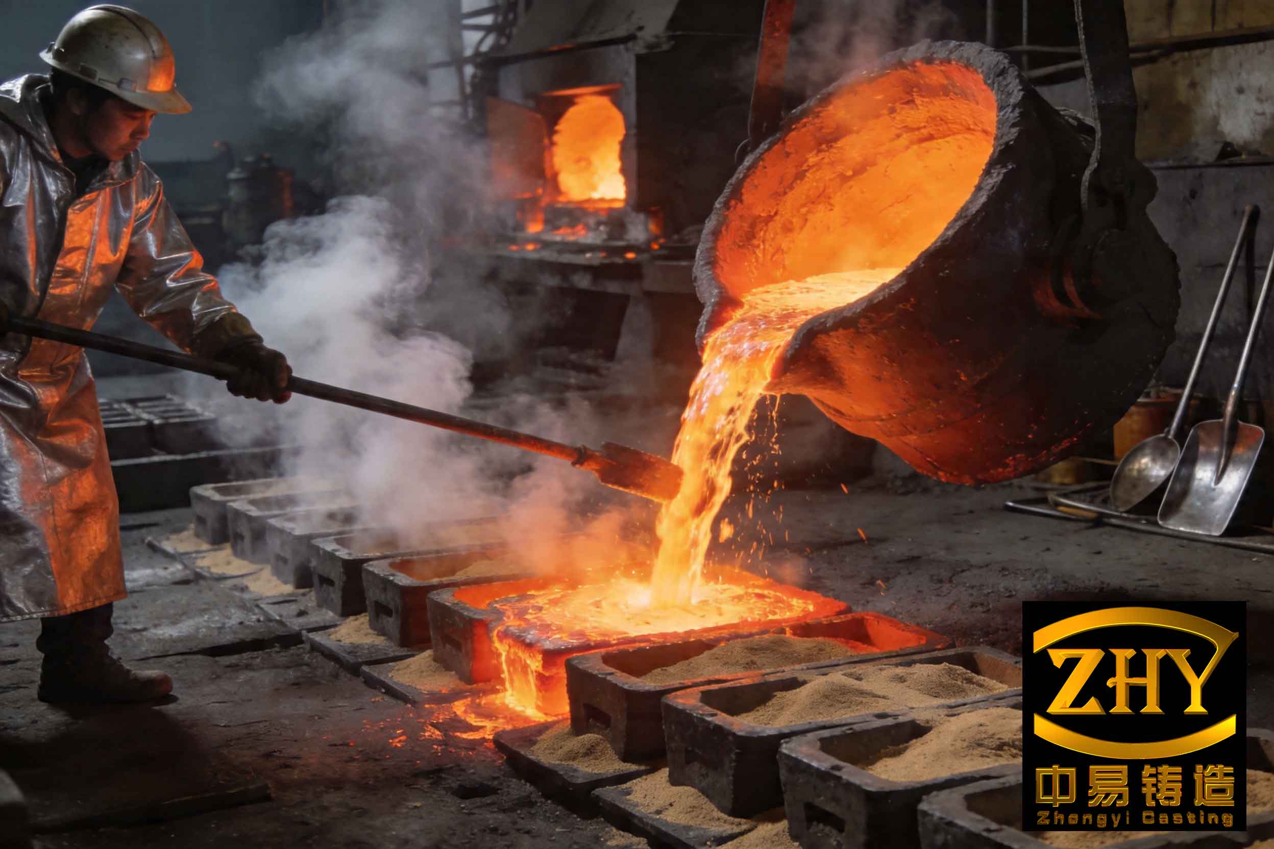
The fundamental principle of hot-mold centrifugal casting involves pouring molten iron from a moving ladle into a high-speed rotating mold. The centrifugal force ($\vec{F_c} = m \omega^2 \vec{r}$) drives the metal against the mold wall, promoting dense solidification. However, this same force acts on non-metallic inclusions and gas bubbles, pushing them radially inwards towards the axis of rotation. The socket region, particularly the D3 face, is characteristically thicker than the pipe barrel. This greater thermal mass results in a slower local cooling rate, extending the time window—the critical “dwell time”—during which impurities can float inward and accumulate. The resulting defect layer is a complex mixture of oxides, sulfides, and micro-porosity, collectively perceived as a **slag inclusion** and porous zone. The severity can be quantified by measuring the average thickness of this layer and the local density relative to the theoretical density of ductile iron. My investigations have systematically deconstructed the influences of molten metal chemistry, treatment, pouring dynamics, and cooling control.
1. The Foundational Role of Molten Metal Chemistry and Cleanliness
The propensity for **slag inclusion** formation is intrinsically linked to the chemical composition of the treated iron. Two elements, magnesium and titanium, are of paramount importance.
1.1 Magnesium Activity and Oxide Formation
Magnesium, essential for nodularization, is highly reactive. Its residual content post-treatment is a double-edged sword. While necessary to prevent fade, excessive residual Mg (>0.060 wt.%) dramatically increases the rate of oxide film formation. The reaction can be simplified as:
$$ 2\text{Mg}_{(in Fe)} + \text{O}_2 \rightarrow 2\text{MgO}_{(s)} $$
This solid MgO film forms at the metal-air interface. During transfer and pouring, this film can break up and be entrained into the bulk metal. Due to its low density ($\rho_{\text{MgO}} \approx 3.6 \text{ g/cm}^3$) compared to iron ($\rho_{\text{Fe}} \approx 7.1 \text{ g/cm}^3$), these particles experience a net radial buoyancy force in the centrifugal field:
$$ F_b \propto (\rho_{\text{Fe}} – \rho_{\text{inclusion}}) \omega^2 r $$
This drives them toward the inner surface. Furthermore, these oxide films act as potent collectors for other inclusions like sulfides (e.g., MgS, CeS), aggregating into larger macro-inclusions. Therefore, maintaining a tight control window for residual magnesium (0.040–0.060%) is the first critical step in minimizing the source of endogenous **slag inclusion**.
1.2 The Detrimental Effect of Titanium
Titanium, often introduced via pig iron, forms very stable, high-melting-point compounds within the melt. The sequence of formation and their approximate melting points highlight the issue:
– Oxides (TiO2, MP ~1843°C) form most readily.
– Nitrides (TiN, MP ~2950°C) and Carbonitrides (Ti(C,N)).
– Carbides (TiC, MP ~3140°C).
– Sulfides (TiS).
These particles, particularly the complex Ti(C,N) and TiC, exist as solid clusters in the iron melt even at pouring temperatures (~1300°C). Their presence significantly increases the apparent viscosity of the molten metal, hindering the coalescence and flotation of other slag particles during holding and making slag removal prior to pouring less efficient. A clear correlation is observed where Ti levels exceeding 0.050 wt.% lead to a measurable increase in melt slag load and a corresponding worsening of socket **slag inclusion**.
1.3 Enhancing Metal Cleanliness Through Thermal Management
The efficiency of slag removal in the induction furnace is not merely a function of skimming; it is governed by the principles of Stokes’ law flotation and thermal kinetics. Increasing the melt temperature and providing sufficient holding time dramatically improves inclusion removal. The terminal velocity of a spherical inclusion rising under gravity (a proxy for its behavior prior to centrifugal casting) is given by:
$$ v_t = \frac{2}{9} \frac{(\rho_m – \rho_i) g r^2}{\eta} $$
where $v_t$ is terminal velocity, $\rho_m$ and $\rho_i$ are densities of metal and inclusion, $g$ is gravity, $r$ is inclusion radius, and $\eta$ is metal viscosity. Higher temperature reduces $\eta$, thereby increasing $v_t$ and speeding up flotation. Furthermore, higher superheat promotes the coalescence of smaller inclusions into larger ones (increasing $r$), which have a much greater $v_t$ (proportional to $r^2$).
My controlled trials quantified this effect. Using a base iron with consistent composition, I varied the holding temperature and time before tapping. The amount of slag removed and the subsequent quality of the socket D3 face were meticulously recorded.
| Furnace Superheat Temp. (°C) | Holding Time (min) | Slag Removed (kg/ton) | Avg. D3 Slag Layer (mm) | Avg. D3 Relative Density (%) |
|---|---|---|---|---|
| 1400 | 0 | ~6.7 | 8.42 | 60.54 |
| 1400 | 5 | ~8.0 | 7.51 | 65.23 |
| 1400 | 10 | ~14.0 | 7.22 | 66.52 |
| 1480 | 10 | ~21.3 | 5.35 | 69.58 |
The data unequivocally shows that higher superheat (1480°C) combined with a 10-minute hold is vastly superior, reducing the **slag inclusion** layer thickness by over 35% compared to a standard 1400°C tap. This practice directly reduces the population of inclusions available to segregate to the socket D3 face.
2. Optimizing Pouring System Dynamics to Minimize Reoxidation and Turbulence
Even with clean metal from the furnace, the pouring system—comprising the ladle, trough, and spout—can be a major source of secondary oxidation and dross generation, leading to exogenous **slag inclusion**. The key variables are pouring position, pouring time for the socket, and metal flow characteristics.
2.1 Pouring Position (Metal Fall Height)
The vertical distance the metal stream falls into the rotating mold impacts both splash and effective filling pressure. A high fall creates significant turbulence, breaking the stream into droplets that oxidize extensively. It also reduces the dynamic pressure head available to force metal into the socket details. Ideally, the pour should be as close to axial as possible. Trials comparing different pour heights relative to the mold axis demonstrate a clear trend: a “zero-drop” pour, where the metal enters nearly tangentially, yields the best results by minimizing reoxidation and maximizing filling pressure to suppress pore formation.
2.2 Socket Pouring Time and Flow Stability
The rate at which the socket portion of the mold is filled, controlled by the ladle tilt speed, influences thermal gradients and inclusion flotation time within the socket cavity itself. Too slow a fill extends the time the first-poured metal remains liquid, allowing more inclusion flotation. Too fast a fill can increase turbulence. An intermediate, controlled fill of approximately 3 seconds for the socket volume proves optimal.
More critical than time alone is the state of the metal in the long (~10m) distribution trough. If the flow is turbulent, “shooting” or “fountaining,” it creates a massive, renewing surface area for oxidation and can erode the refractory coating of the trough, introducing mechanical **slag inclusion**. A smooth, coherent, “lazy river” flow is essential.
The table below synthesizes the interactive effects of these pouring parameters on the final socket quality, using metal prepared under the optimal furnace conditions (1480°C superheat, 10 min hold).
| Pour Height (mm) | Socket Pour Time (s) | Flow Character in Trough | Avg. D3 Slag Layer (mm) | Avg. D3 Relative Density (%) |
|---|---|---|---|---|
| 0 | 3 | Turbulent, Splashing | 5.11 | 78.99 |
| 50 | 3 | Turbulent, Splashing | 6.15 | 66.87 |
| 100 | 3 | Turbulent, Splashing | 7.63 | 60.21 |
| 0 | 3 | Smooth, Coherent | 4.52 | 85.22 |
| 50 | 3 | Smooth, Coherent | 6.13 | 69.28 |
| 100 | 3 | Smooth, Coherent | 6.95 | 65.52 |
The synergy of a zero-drop pour, a 3-second socket fill, and smooth trough flow delivers a socket with a **slag inclusion** layer under 5mm and a relative density exceeding 85%. This represents a monumental improvement over the baseline process.
3. The Decisive Factor: Controlling Solidification Through Cooling Rate
Even with optimized metal and pouring, a slow-cooling socket will still allow significant defect band formation. The most powerful lever to suppress **slag inclusion** and porosity segregation is to accelerate the solidification of the socket region. This is achieved by manipulating the mold’s insulating coating thickness and the intensity of external water spray cooling.
The governing principle is the reduction of the “dwell time” $t_d$ available for inclusion flotation. This time is inversely related to the average cooling rate $(\frac{dT}{dt})_{avg}$ from pouring temperature $T_p$ to solidus $T_s$:
$$ t_d \propto \frac{T_p – T_s}{(\frac{dT}{dt})_{avg}} $$
Increasing $(\frac{dT}{dt})_{avg}$ directly reduces $t_d$, limiting the distance an inclusion can travel via Stokes’ law in the centrifugal field before being entrapped by the advancing solidification front.
The cooling rate is controlled by the thermal resistance of the system. The dominant resistances are:
1. The mold-coating interface and coating itself.
2. The mold wall.
3. The mold-water spray interface.
Reducing the coating thickness minimizes resistance (1). Increasing water flow rate and efficiency minimizes resistance (3). The combined effect on the cooling rate and resultant quality is dramatic.
| Mold Coating Thickness (mm) | Water Spray Intensity (L/min·m²) | Avg. Cooling Rate (°C/s)* | Avg. D3 Slag Layer (mm) | Avg. D3 Relative Density (%) |
|---|---|---|---|---|
| 1.0 | 30-37 | 2.22 | 6.12 | 68.23 |
| 0.9 | 30-37 | 2.58 | 5.25 | 71.56 |
| 0.8 | 37-45 | 3.25 | 4.23 | 75.12 |
| 0.7 | 37-45 | 3.56 | 3.56 | 78.12 |
| 0.6 | 37-45 | 4.12 | 2.96 | 88.93 |
*Measured in the socket region via thermal analysis.
By pushing the cooling rate to approximately 4.12°C/s, the **slag inclusion** layer thickness is halved and the density approaches 90% of theoretical. It is crucial to balance this with metallurgical needs; excessively high cooling rates can promote carbides in the pipe wall. A coating thickness of 0.6 mm and a water spray intensity of 37-45 L/min·m² have been established as the optimal compromise.
4. Addressing Mechanical Slag Inclusion Sources
Process discipline in areas not directly related to metal physics is equally vital. These are sources of mechanical **slag inclusion**:
- Mold Coating Integrity: A weak or improperly applied mold coating can spall off when hit by the molten metal stream. This debris is instantly entrained, creating large, macroscopic slag patches. Ensuring correct coating material composition, application pressure, and drying is non-negotiable.
- Trough/Spout Lining Stability: The refractory lining in the metal distribution system must withstand thermal shock and erosion. A lining that cracks or washes away contributes direct refractory particles to the **slag inclusion** count.
- Core Coating Dryness: The sand core defining the socket’s internal shape is coated with a refractory wash. If this coating is not thoroughly dried, contact with molten metal causes steam generation and explosive flaking, introducing defects at the very location (D3 face) we are trying to protect.
5. The Integrated, Optimized Process Protocol
Based on the systematic investigation outlined, the following integrated process parameters constitute the definitive recipe for eliminating **slag inclusion** and porosity defects in the socket of hot-mold centrifugal ductile iron pipes:
| Process Stage | Optimized Parameter | Target / Control Limit | Rationale |
|---|---|---|---|
| Metal Chemistry & Treatment | Residual Mg | 0.050 – 0.070% | Balances nodularity with minimized oxide formation. |
| Ti Content | < 0.050% | Prevents viscous melt and high-MP inclusions. | |
| Furnace Superheat & Hold | 1480°C for 10 min | Maximizes inclusion flotation and removal. | |
| Pouring Temperature | 1330 – 1350°C | Provides sufficient fluidity without excessive oxidation. | |
| Pouring Dynamics | Pouring Height | Axial / “Zero-Drop” | Minimizes turbulence and reoxidation; maximizes filling pressure. |
| Socket Fill Time | ~3 seconds | Optimal balance between thermal gradient and turbulence. | |
| Metal Flow in Trough | Smooth, Coherent, Non-Turbulent | Prevents secondary oxidation and lining erosion. | |
| Solidification Control | Mold Coating Thickness | 0.6 mm | Minimizes thermal barrier to accelerate cooling. |
| Water Spray Cooling | 37 – 45 L/min·m² | Extracts heat rapidly to shorten inclusion flotation time. | |
| Auxiliary Controls | Coating & Core Dryness | High Strength, Fully Dried | Eliminates sources of mechanical slag inclusion. |
The implementation of this optimized protocol has proven to be transformative. The **slag inclusion** layer on the socket D3 face is consistently controlled to be less than 2.5 mm, with a relative density exceeding 91%. The surface is sound and dense, meeting the highest standards for both pressure integrity and visual quality.
6. Conclusion
The mitigation of **slag inclusion** and porosity defects in hot-mold centrifugal cast pipe sockets is not a matter of a single corrective action but a systematic optimization of the entire process chain. The defect arises from the natural tendency of impurities to segregate under centrifugal force during the extended solidification time of a heavy section. The strategy for prevention is threefold: first, minimize the source by controlling reactive elements (Mg, Ti) and employing rigorous superheating and holding for slag removal; second, protect the metal during transfer by optimizing pouring dynamics to prevent reoxidation and turbulence; and third, and most critically, reduce the available time for segregation by aggressively accelerating the cooling rate of the socket through thin coatings and intensive spray cooling. Attention to ancillary factors like coating integrity ensures that mechanical **slag inclusion** sources are eliminated. This comprehensive, physics-based approach delivers robust, high-quality castings suitable for demanding infrastructure applications.