
The casting process plan mainly includes the selection of molding method, pouring position and parting surface. The determination of casting process scheme is based on the full analysis of casting process characteristics of part structure, combined with actual production equipment and technical conditions.
Pouring position refers to the state and position of the casting in the mold during pouring. The selection of pouring position directly determines the difficulty of molding operation, the overall quality of the casting and the final dimensional accuracy. When selecting the pouring position, the solidification characteristics, technical requirements, casting structure characteristics and the actual production conditions of the casting manufacturer are generally considered, and the parts prone to defects need to be estimated and corresponding process preventive measures should be taken. When selecting the pouring position of the feeding cylinder, the following principles should be considered comprehensively
(1) The important machining surface is vertical inclined or downward to reduce the possibility of defects.
According to the analysis of formation mechanism and distribution location of common pores and slag inclusions, it is less likely that similar defects appear on the downward or vertical side. The B, G, h, I and j surfaces in Fig. 2-1 are the main machining surfaces during the assembly of the inlet cylinder, in which the B and j surfaces are the matching assembly surfaces of the upper and lower half cylinders, and the G surface is the assembly surface of the inlet cylinder and the compressor cylinder. It is preferred to be the side of the pouring position or the downward position of the pouring position. In the non machined surface, the D and e surfaces of the air inlet side have large areas, which are easy to produce surface defects such as slag inclusion and air holes on the surface.
(2) The selection of pouring position must be conducive to the filling and feeding of castings to meet the requirements of compact structure.
For castings with thin wall in the structure, the thin wall part should be placed at the lower part of the pouring position. According to the structure analysis of the inlet cylinder casting, the thickness and thickness of the inlet cylinder wall are very uneven. The area formed by a-b-c three sides is the relatively thin area in the casting, so the thin-wall position should be placed at the lower part of the pouring position. The area formed by g-h-j three faces has a wall thickness of 400mm and a large cross-sectional area. According to the solidification characteristics of nodular cast iron, it is difficult to feed the area. This surface is used as the upper part of the pouring position, which is convenient to set up a riser for liquid feeding.
(3) The modeling operation process is simple and easy to control, which meets the requirements of dimensional accuracy.
Because of the special structure and high dimensional accuracy of the inlet cylinder casting, it can only be realized by means of core assembly modeling. The accuracy and operability of core setting operation, size detection and sand core positioning must be considered in the process design and determination. Meanwhile, hanging core or cantilever core should be avoided. The area formed by several surfaces of a-b-c-d-e depends on the accurate positioning and assembly of sand core. In order to place the sand core accurately and stably, the positioning core head and preset sand core fastening point are set in the lower mold of the mold to facilitate the positioning and fastening of the sand core.
Considering the above factors (1) ~ (3) and combining with the actual production experience of similar heavy parts, the pouring position as shown in Fig. 1 is finally selected and determined.
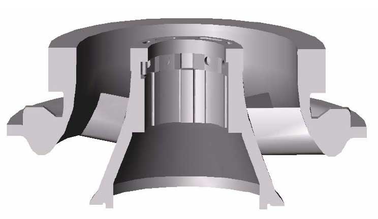
The pouring position selected according to this scheme is not only convenient for liquid feeding to the thick part of stator blade flange by setting riser, but also convenient for setting and placing cold iron in other parts, so as to create conditions for forming balanced solidification temperature gradient, and achieve the pre designed feeding channel and solidification temperature gradient. At the same time, the pouring position is convenient for the setting and placement of bottom return and ladder type gating system, reducing the risk of surface quality problems caused by non machining surface and important processing surface. Finally, the slag and gas in molten iron can float up to the upper end face, and preset riser position can fully ensure the quality of casting.