
In my experience working with high-performance commercial vehicle engines, the continuous evolution of power output and emission regulations has driven a significant shift in material requirements for core components like cylinder heads. The transition from traditional gray iron HT250 to HT300, and ultimately to vermicular graphite iron RuT450, represents an increase in tensile strength by over 80% and nearly double the yield strength. While this enhances engine durability and efficiency, it introduces formidable casting challenges, chief among them being the persistent issue of shrinkage defects in isolated hot spots. Shrinkage in casting, particularly for vermicular graphite iron, is exacerbated by its solidification behavior, which tends toward a mushy type similar to ductile iron, leading to greater contraction tendencies. This problem is amplified in heavy-duty, large-horsepower engine cylinder heads designed with thin-walled, lightweight structures, where features like fuel injector holes, valve guide holes, and fastener bolt holes form numerous isolated thermal junctions. Due to product geometry, establishing effective feeding channels for these areas is inherently difficult, making shrinkage in casting a critical concern.
Most foundries initially employed the sandwich method for vermicularization treatment coupled with rapid metallographic testing for vermicularity rate. However, since the 1990s, advanced processes like wire-feeding vermicularization and detection technologies such as SinterCast and OCC have been adopted for producing vermicular graphite iron cylinder blocks, heads, and exhaust manifolds. These advancements have stabilized the vermicularity rate from a range of 50–95% to a more consistent 80–95%, improving material homogeneity and somewhat reducing the propensity for shrinkage in casting. Our facility began mass-producing vermicular graphite iron exhaust manifolds for EQ140 trucks in 1983 and later applied RuT450 material to cylinder heads and blocks for DDi series commercial engines around 2009. Early production of DDi75 cylinder heads utilized a horizontal pouring process with insulating risers, which proved relatively mature in terms of process and quality. In 2018, to enhance yield rates, reduce costs, and boost production efficiency—key QCD metrics—we transitioned to a vertical pouring process with two castings per mold for a new large-horsepower engine cylinder head. This vertical pouring approach, however, highlighted the acute challenge of shrinkage defects in isolated hot spots, necessitating urgent resolution.
The cylinder head in question weighs approximately 150 kg, with overall dimensions of 1,070 mm × 340 mm × 165 mm. Its structure includes four rows of φ29 mm bolt bosses from the intake to exhaust sides, averaging eight sets per cylinder, and four sets of φ26 mm intake and exhaust guide pillars around the fuel injector area per cylinder. A main oil channel of φ20 mm running from front to rear intersects with guide valve seats and camshaft mounting bases, creating cross-shaped thermal junctions. These features result in numerous isolated hot spots: six fuel injector holes, 24 valve guide holes, and 38 fastener bolt holes, all lacking efficient feeding paths. The material specification requires RuT450 with a vermicularity rate ≥80% on the combustion chamber face, a tensile strength ≥430 MPa, and a hardness of HBW 200–250. Critically, machined surfaces of injector holes, guide holes, and bolt holes must be free from shrinkage defects. The chemical composition is as detailed in the table below.
| Alloy Grade | C (%) | Si (%) | Mn (%) | P (%) | S (%) | Cu (%) | Sn (%) |
|---|---|---|---|---|---|---|---|
| RuT450 | 3.6–3.9 | 1.8–2.3 | 0.4–0.9 | ≤0.07 | ≤0.025 | 0.4–1.2 | 0.06–0.13 |
This composition, combined with the complex geometry, severely impairs castability, making shrinkage in casting a prevalent issue in these isolated regions.
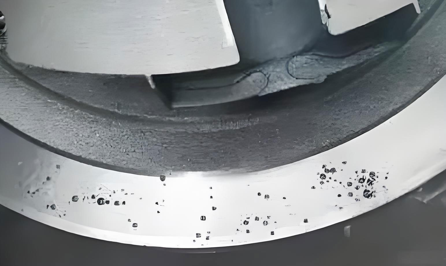
Our initial process employed vertical pouring with a one-mold-two-castings configuration on an HWS static pressure molding line. The gating system was a bottom-pour single-layer design, with runners entering from the parting plane along the side of the base core towards the exhaust-side bottom, then feeding into the cavity through six ingates. External chills of φ20 mm × 20 mm were placed in the core corresponding to bolt holes. Iron melt treatment involved the sandwich method with rapid metallographic testing initially, but we later upgraded to wire-feeding vermicularization with OCC detection for formal production. Pouring was done via a KW automatic pouring machine with a maximum capacity of 2.8 tonnes per ladle and a temperature range of 1,380–1,420°C. Despite these measures, machining revealed significant shrinkage porosity in bolt holes and guide holes, especially between cylinders 3 and 4, where shrinkage occurred 50–70 mm from the bottom plate at junctions with water jacket separators. Analysis indicated that the runner flow along the bottom side worsened cooling conditions in adjacent thick sections, while upper melt failed to provide adequate feeding, leading to widespread shrinkage in casting.
To address this, we embarked on a series of iterative improvements. The first modification involved replacing external cylindrical chills with longer bar-shaped ones at lower bolt holes and adding internal ring chills in guide holes, alongside implementing a hot riser at the second row of bolt holes near the parting plane. This reduced shrinkage in the riser-fed area but left persistent defects in the third row, and ring chills caused fusion issues and gas holes. We realized that while risers could feed near-bottom hot spots, their effectiveness diminished for deeper regions due to distance constraints, highlighting the limitations of relying solely on feeding for shrinkage in casting.
The second approach focused on reducing geometric thermal mass by casting holes with a 2 mm allowance per side—semi-length holes for bolts up to 70 mm from the bottom and through-holes for guides. This diminished shrinkage in the cast sections, but porosity reappeared near the hole tops, and dimensional instability from core deformation under high temperatures posed machining risks. The effective reduction in thermal modulus was limited because cores embedded in iron melt still impeded heat dissipation. This underscored that merely altering geometry wasn’t sufficient to eliminate shrinkage in casting in such isolated zones.
The third and most successful strategy integrated internal and external chills to accelerate cooling at the core of hot spots. We evaluated various chill materials based on relative cooling capacity, as summarized below, where silicon sand’s cooling ability is normalized to 1.
| Chill Material | Copper | Steel | Graphite | Steel Shot | Chromite Sand | Silicon Sand |
|---|---|---|---|---|---|---|
| Relative Cooling Capacity | 4.05 | 3.95 | 3.34 | 1.89 | 1.56 | 1 |
Considering cost and manufacturability, we tested steel, cast iron, and graphite chills, with steel chill rods showing the best results. By embedding these in bolt and guide holes, shrinkage rates dropped by over 90% compared to the initial process. We further optimized this using CAE solidification simulation to analyze chill extension, modeling heat accumulation with the formula for thermal diffusivity α: $$α = \frac{k}{ρ c_p}$$ where k is thermal conductivity, ρ is density, and c_p is specific heat capacity. The simulation revealed that lengthening chills equalized temperature distribution across ends, enhancing sustained heat transfer from the bottom side. The temperature gradient before and after extension can be described by Fourier’s law: $$q = -k \nabla T$$ where q is heat flux and ∇T is temperature gradient. Post-extension, the gradient near the bottom reduced, effectively mitigating shrinkage in casting.
Our final production process combined vertical pouring with side-gating systems, internal chill cores in injector holes, and internal chill rods in bolt and guide holes. The chills were machined out post-casting, ensuring normal vermicularity and matrix structure in adjacent areas. This multi-pronged approach proved effective in mass production, virtually eliminating shrinkage defects in all critical isolated hot spots. The key takeaway is that for vermicular graphite iron cylinder heads with numerous isolated thermal junctions under vertical pouring, a holistic strategy is essential: risers for feedable regions, chills for deep-seated hot spots, and, where feasible, cast holes to reduce thermal mass. Each element addresses different aspects of shrinkage in casting, and their synergy is crucial for success.
In reflecting on this journey, I’ve come to appreciate the nuanced nature of shrinkage in casting. It’s not merely a material issue but a complex interplay of geometry, process parameters, and thermal management. The modulus M, defined as volume V divided by cooling surface area A ($$M = \frac{V}{A}$$), is a critical parameter for hot spots. For isolated features like bolt holes, M can be high, leading to prolonged solidification and shrinkage. By applying chills, we effectively increase A locally, reducing M and accelerating solidification. Additionally, the solidification contraction β, given by $$β = \frac{ρ_l – ρ_s}{ρ_l} \times 100\%$$ where ρ_l and ρ_s are liquid and solid densities, respectively, influences the feeding demand. For vermicular graphite iron, β is higher than for gray iron, necessitating robust feeding or chilling to compensate.
To generalize our findings, I’ve tabulated the effectiveness of various countermeasures against shrinkage in casting for different defect types, based on our trials and industry data. This table summarizes the relative impact, with scores from 1 (low) to 5 (high).
| Countermeasure | Effect on Surface Shrinkage | Effect on Subsurface Shrinkage | Effect on Internal Shrinkage | Cost Impact | Implementation Complexity |
|---|---|---|---|---|---|
| Hot Risers | 4 | 3 | 2 | Medium | Low |
| External Chills | 5 | 4 | 3 | Low | Low |
| Internal Chills | 3 | 5 | 5 | Medium | High |
| Cast Holes | 4 | 4 | 3 | High | Medium |
| Gating Optimization | 3 | 3 | 2 | Low | Medium |
| Material Control (e.g., Vermicularity) | 2 | 3 | 4 | Medium | High |
This highlights that internal chills are particularly potent for internal shrinkage in casting, albeit with higher complexity. Moreover, process stability hinges on controlling iron melt quality. We maintained a rigorous three-check system for vermicularity: melt testing via OCC, attached sample testing, and casting ultrasonic or acoustic inspection, ensuring ≥80% vermicularity. This control indirectly reduces shrinkage tendency by promoting a more favorable graphite morphology, as vermicular graphite has lower contraction than spheroidal graphite but higher than flake graphite. The relationship can be approximated by a shrinkage factor S_f: $$S_f = f_v \cdot β_v + f_s \cdot β_s + f_g \cdot β_g$$ where f_v, f_s, f_g are volume fractions of vermicular, spheroidal, and graphite types, and β_v, β_s, β_g are their respective contraction coefficients. By maximizing f_v, we minimize S_f, thereby mitigating shrinkage in casting.
Another aspect we explored was the role of pouring temperature T_p. Higher T_p can improve fluidity but exacerbates shrinkage due to greater thermal contraction. We optimized T_p to 1,400°C ± 20°C, balancing these factors. The thermal gradient G during solidification, critical for feeding, is given by $$G = \frac{T_l – T_s}{L}$$ where T_l is liquidus temperature, T_s is solidus temperature, and L is characteristic length. Vertical pouring alters G compared to horizontal, often reducing it in isolated regions, which aggravates shrinkage in casting. Our side-gating redesign helped restore favorable gradients.
Throughout this project, shrinkage in casting remained our focal challenge. It’s a defect that not only compromises mechanical integrity but also leads to costly scrap and rework. By systematically integrating risers, chills, and process controls, we transformed a problematic casting into a reliable product. This experience underscores that in modern foundry engineering, addressing shrinkage in casting requires a multifaceted approach, blending traditional wisdom with advanced simulation and material science. As engines continue to evolve, such strategies will be vital for manufacturing high-integrity components efficiently.
Looking ahead, we plan to further refine our models for predicting shrinkage in casting. One promising avenue is using machine learning algorithms to correlate process parameters with defect occurrence, based on historical data. For instance, a linear regression model could predict shrinkage probability P_s: $$P_s = a_0 + a_1 \cdot M + a_2 \cdot β + a_3 \cdot G + a_4 \cdot T_p$$ where a_i are coefficients derived from data. This would enable proactive adjustments, minimizing trials. Additionally, we’re investigating novel chill materials with higher cooling capacities, such as copper alloys, though cost-benefit analysis is ongoing. The fundamental goal remains: to eradicate shrinkage in casting through continuous innovation and holistic process design.
In conclusion, the battle against shrinkage in casting, especially in vermicular graphite iron cylinder heads with isolated hot spots, is won through a combination of feeding, chilling, and geometric optimization. Vertical pouring poses unique challenges, but with careful application of internal and external chills, coupled with controlled vermicularization, defects can be effectively eliminated. This journey has reinforced that shrinkage in casting is not an insurmountable problem but a solvable one with the right toolkit and persistent effort. As we push the boundaries of engine performance, these lessons will guide our future endeavors in producing high-quality cast components.