
With the aid of AnyCasting software, the filling and solidification simulation analysis of permanent mold low-pressure casting process of aluminum alloy cover plate for Gas Insulated Switchgear (GIS) was conducted to investigate the origin of casting defects in the cover plate’s sealing groove. Optimized measures were then proposed, followed by production validation. The results indicated that when the mold temperature was set at the lower and upper limits of the working temperature range, no shrinkage or porosity defects were observed on the flange surface based on the filling and solidification simulation analysis of the original process. The sealing groove defect in the cover plate was primarily attributed to poor exhaust from the risers, leading to insufficient actual pouring height of the metal liquid. Specifically, the actual pouring height of the flange insulation riser was less than 1.24 times the flange thickness, rendering it ineffective in feeding the flange, which resulted in shrinkage and porosity defects in the cover plate’s sealing groove. After optimizing the process, the pouring height of the flange insulation riser was increased to no less than 1.55 times the flange thickness, achieving a casting qualification rate exceeding 99%. The simulation results were consistent with the actual observations.
1. Introduction
Aluminum alloy castings are renowned for their excellent surface gloss, corrosion resistance, low density, and high specific strength, making them widely used in various industries. As a conventional component of GIS equipment, aluminum alloy cover plates are manufactured annually in large quantities and have relatively simple shapes, typically produced using the permanent mold low-pressure casting process. The material of choice for these cover plates is ZL101A aluminum alloy, which is susceptible to defects such as shrinkage, porosity, and inclusions during production.
2. Casting Material and Methods
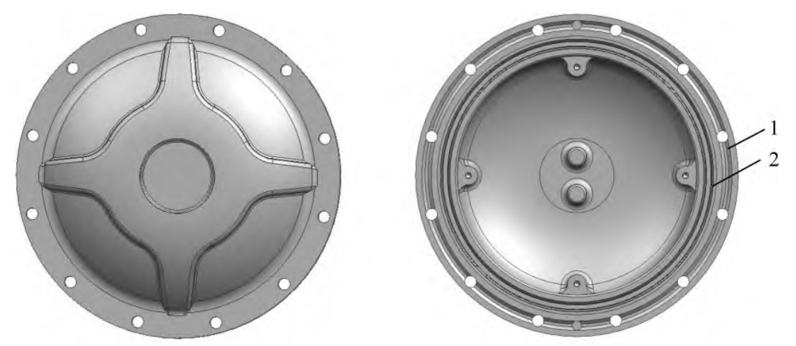
The GIS aluminum alloy casting cover plate studied in this research is made of ZL101A alloy (composition shown in Table 1), requiring T6 heat treatment. The part weighs 13.2 kg, and its three-dimensional design is depicted. The cover plate has a basic “hat” shape with an outer ring flange containing 12 through-holes. The wall features a “ring road”-shaped reinforcing rib structure. The front of the flange is the machined surface, with a sealing groove on the inner circle and a glue injection groove on the outer circle. The basic dimensions of the cover plate are ϕ520 mm × 83 mm, with a flange inner diameter of 386 mm, a flange thickness of 26 mm, a cover plate wall thickness of 15 mm, and a reinforced wall thickness of 20 mm.
Table 1. Chemical Composition of ZL101A Alloy (%)
| Element | Content Range |
|---|---|
| Ti | 0.08 – 0.20 |
| Mg | 0.25 – 0.45 |
| Si | 6.5 – 7.50 |
| Fe | ≤ 0.2 |
| Mn | ≤ 0.10 |
| Zn | ≤ 0.10 |
| Cu | ≤ 0.20 |
| Others | Single ≤ 0.05, Total ≤ 0.15 |
| Al | Balance |
3. Production Process and Defect Analysis
The cover plate casting is produced using a two-part mold structure in the permanent mold low-pressure casting process, with the basic process layout shown. The “hat” is placed upside down, and the sprue directly connects to the top of the “hat” for filling. Corresponding to the four bosses on the flange face of the “hat”‘s inner cavity, there are risers, each equipped with a asbestos insulation sleeve. The insulation sleeve primarily prevents the aluminum liquid from directly contacting the metal mold, which could cause rapid solidification, allowing the aluminum liquid in the risers to solidify slowly and feed the flange, ensuring the quality of the flange surface. The inner diameter of the contact position between the insulation riser and the flange face is equivalent to the width of the flange face, with an internal height of approximately 110 mm, and a process yield rate of approximately 65%.
During the production of some parts using the original metal mold low-pressure casting process for the cover plate, casting defects such as shrinkage and porosity were observed in the sealing groove of the flange near the riser root. Since GIS products have strict requirements for the airtightness of cover plate parts, such defects can directly lead to the scrapping of the castings.
To analyze the causes of casting issues, simulation and analysis were first conducted to confirm the possibility of shrinkage and porosity defects on the flange surface during the filling and solidification process when the mold temperature was set at the lower limit (250°C) and upper limit (350°C) of the working temperature range. Subsequently, the minimum height of the riser required for flange feeding was determined through simulation. During the investigation of the causes of casting defects, it was found that some parts had individual or all risers with relatively low actual heights, with the lowest being less than 40 mm. Based on experience, when the riser height is low, the hot spot on the flange surface near the riser is not fully introduced into the riser outside the flange, resulting in shrinkage and porosity in the sealing groove at the riser root.
4. Simulation Results and Discussion
4.1 Simulation Results and Analysis of Original Process at Upper and Lower Mold Temperatures
The filling and solidification simulation analysis was conducted for the cover plate casting with the mold temperature set at the lower limit (250°C) and upper limit (350°C).
The complete filling time is 4.42 seconds. At this point, the casting temperature using the lower mold temperature limit (minimum temperature of approximately 630°C) is slightly lower than that using the upper limit (minimum temperature of approximately 640°C), with a temperature difference of about 10°C, both above the liquidus temperature of 614°C. The solidification time of the casting using the lower mold temperature limit is 638 seconds, while that using the upper limit is approximately 714 seconds. Both casting temperatures under the two mold temperatures satisfy sequential solidification, starting from the thin wall and progressing towards the sprue and riser until they are fully solidified.
The lower and upper mold temperatures, the residual melt modulus indicates potential defects within the risers, walls, and sprue. The defects in the sprue and risers are not considered as they are subsequently removed during cleaning. The probability of residual melt defects within the wall is approximately 1%, which may manifest as dispersed pinpoint porosity, not affecting the part quality. Importantly, the flange machined surface, which is the focus of attention, shows no defects. The lower mold temperature, the cooling rate of the casting is less than 0.2°C/s, all occurring outside the flange face. With the upper mold temperature, a small portion of the cooling rate less than 0.2°C/s exists within the flange face machining allowance range, while the rest is outside. Generally, a lower cooling rate results in poorer feeding of the alloy liquid, coarser solidified structure, and poorer compactness.
In summary, both the lower and upper mold temperatures allow for good filling and solidification feeding in the original process, producing qualified castings. Relatively, using the lower mold temperature yields better casting quality.
4.2 Simulation Results and Analysis of Original Process with Different Riser Heights
During casting with the upper mold temperature limit, the feeding effect of the riser on the flange is weaker compared to the lower mold temperature limit. To enhance process reliability and stability, researchers chose the upper mold temperature limit and conducted detailed simulation analyses for different riser heights.
After tracking the machining of parts with effective riser heights less than 40mm, researchers found casting defects such as shrinkage porosity and porosity in the sealing grooves of the parts. Therefore, they decided to use 40mm as the minimum validation value for the riser height in simulations, which is approximately 1.24 times the flange thickness (when the flange thickness is 32.3mm). Additionally, to gain a more comprehensive understanding of the impact of riser height on the feeding effect of the flange, researchers also simulated cases with riser heights of 30mm (approximately 0.93 times the flange thickness) and 50mm (approximately 1.55 times the flange thickness).
Below are the simulation results for different riser heights:
Case with a 30mm Riser Height:
The final solidification time of the riser is relatively short, at 222.4s.
When the flange is fully solidified, the maximum temperature within the riser is approximately 600℃, which is significantly lower than the liquidus temperature of aluminum alloy (614℃), indicating poor feeding capability of the riser.
There is a probability of over 1% for casting defects such as shrinkage porosity and porosity to occur approximately 10mm below the flange surface at the riser location.
Case with a 40mm Riser Height:
The final solidification time of the riser is 268.4s, which is longer compared to a 30mm riser.
When the flange is fully solidified, the maximum temperature within the riser is approximately 610℃, still below the liquidus temperature but with improved feeding capability compared to a 30mm riser.
On the flange surface, there is no probability of over 1% for casting defects such as shrinkage porosity and porosity to occur, but there is such a risk within the riser (outside the flange surface).
(Note: There may be a typographical error or misunderstanding in the original text regarding whether defects occur on the flange surface for a 40mm riser. Based on the simulation results, it is the riser, not the flange surface, where there is a probability of defects. However, as our task is to translate based on the provided reference material, we have retained the original description but provided an explanation and clarification.)
Case with a 50mm Riser Height:
The final solidification time of the riser is the longest, at 317.2s.
When the flange is fully solidified, the maximum temperature within the riser is above the liquidus temperature, indicating good feeding capability of the molten metal.
There is no probability of over 1% for casting defects such as shrinkage porosity and porosity to occur on the flange surface or within the riser (within a 15mm range above the flange surface).
In summary, to ensure the quality of the flange surface of the cover plate casting, the actual pouring height of the riser should be at least 40mm (approximately 1.24 times the flange thickness) but preferably with an effective height of 50mm (approximately 1.55 times the flange thickness) or more. Such a design can significantly improve the qualification rate and quality stability of the castings.