1.Analysis of filling process
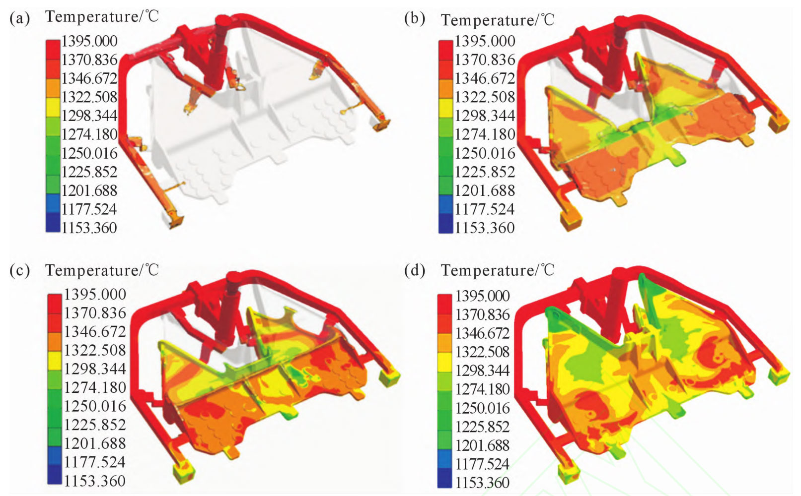
According to the process parameters set earlier, the saddle was numerically simulated, and Figure 1 shows the temperature field during the saddle filling process. In the early stage of mold filling, the metal liquid flows from the vertical sprue to the horizontal sprue and then into the six inner sprues, as shown in Figure 1 (b). It can be seen that the metal liquid gradually flows into the lower cavity of the large thin-walled casting, and the temperature of the lower cavity of the pedestal exceeds the liquidus temperature and reaches over 1360 ° C. It still remains in a liquid state. As the filling process continues, the liquid level in the saddle cavity gradually rises, as shown in Figure 1 (c). When the filling time is s, the lower mold of the large thin-walled casting is fully filled, and the temperature in the thin-walled area of the saddle cavity has decreased to 1320 C. The position near the inner gate is still 1360 C. As shown in Figure 1 (d), the entire pouring process is about to be completed. As the saddle cavity is hollow, the temperature at the edge of the saddle cavity drops to 1290C. The large thin-walled casting mainly adopts bottom injection and also has layered injection. During the filling process, the metal liquid flow rate is stable, and there is no splashing or turbulence phenomenon of the iron liquid throughout the process. The metal liquid can fully fill the entire saddle cavity.
2. Analysis of Solidification Process
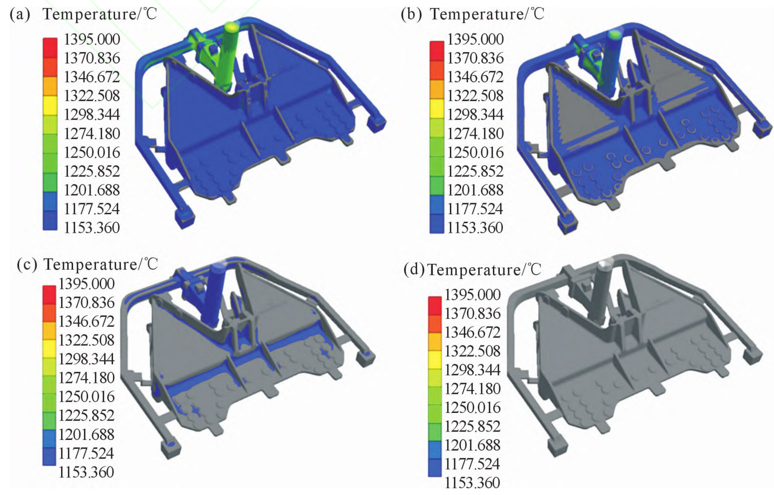
By analyzing the solidification process of large thin-walled castings, the solidification sequence and the location of isolated melt pool zones can be observed, providing corresponding guidance for predicting shrinkage porosity and shrinkage defects. The analysis of the solidification process of saddle casting is shown in Figure 2. From Figure 2 (a), it can be seen that during the initial solidification, the edges of the saddle cavity and the reinforcing ribs begin to solidify first. In Figure 2 (b), the saddle temperature continues to decrease, and the cavity of large thin-walled castings begins to cool down. In Figure 2 (c), most of the saddle cavity has completed solidification, and an isolated liquid phase zone appears at the limit hook device. Due to the presence of a hot spot at this position and the closure of the molten iron feeding channel at the highest position of the exhaust hole, effective feeding cannot be obtained, and shrinkage porosity defects are easily formed. From Figure 2 (d), it can be seen that the saddle has fully solidified.
3. Prediction of shrinkage porosity and porosity
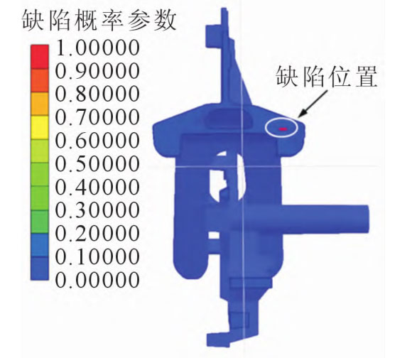
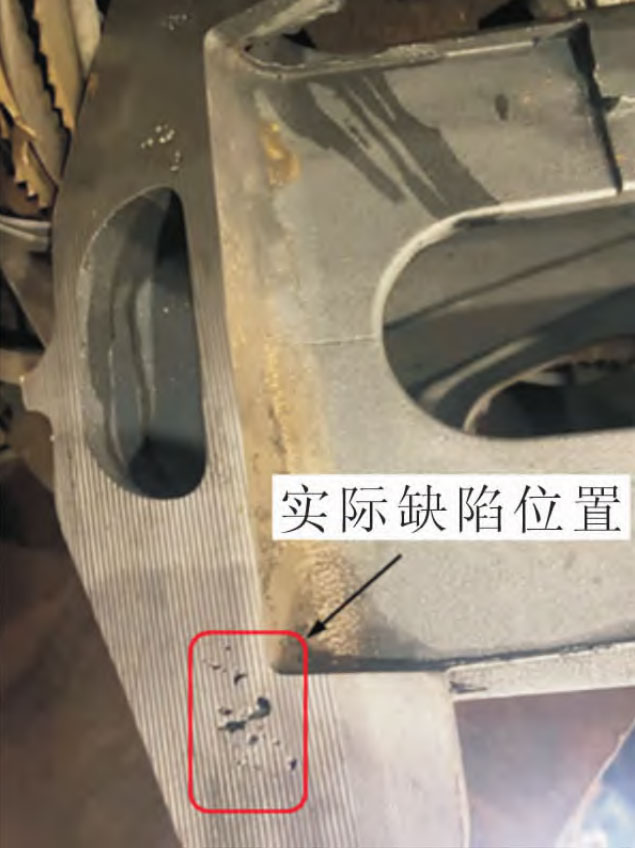
Based on the analysis of the temperature field during the solidification process of large thin-walled castings, it is believed that shrinkage porosity and porosity defects are prone to occur at the limit hook of large thin-walled castings. Figure 3 shows the location of shrinkage porosity and porosity defects in large thin-walled castings predicted by AnyCasting simulation software, with a total volume of approximately 0.32 cm. The defect location is mainly distributed at the limit hook device of large thin-walled castings, which is easy to produce hot spots and is the final solidification area, leading to the defect that the isolated liquid phase area can not be effectively fed. This is consistent with the results of solidification process simulation simulation. The initial casting process scheme is used for trial casting test, and the trial casting is cut and tested, as shown in Figure 4. Shrinkage porosity and shrinkage cavity defects are found on the limit hook device, which are basically consistent with the defect positions in the simulation results, proving the reliability of simulation results of large thin-walled castings during mold filling and solidification process simulation.