
Abstract:
This paper focuses on the simulation and optimization of the V-process casting technology for high chromium cast iron impellers, addressing issues such as shrinkage and porosity defects. Through a combination of numerical simulation and experimental research, the temperature field, solidification process, and defects during casting were analyzed. The relationship between shrinkage and porosity defects and casting structure and process parameters was revealed. By utilizing heating risers and adding external chillers, the occurrence of shrinkage and porosity was effectively reduced. Based on production practice, the optimal V-process casting parameters for high chromium cast iron impellers were determined, and qualified castings were successfully produced, providing a theoretical basis and technical support for mass production.
1. Introduction
High chromium cast iron, due to its excellent wear resistance and corrosion resistance, has been widely used in pumps, hydraulic machinery, and other fields. However, its brittleness and poor casting performance make it prone to defects such as cracks, shrinkage, and porosity during the casting of complex structures like impellers, affecting casting quality and production efficiency. The V-process casting technology, as an advanced casting method, offers advantages such as smooth mold filling, precise casting dimensions, and high surface finish, particularly suitable for the production of complex structural castings. This paper presents a study on the simulation and optimization of the V-process casting technology for high chromium cast iron impellers.
2. Technical Requirements and Initial Casting Process of High Chromium Cast Iron Impeller Castings
2.1 Structure and Technical Requirements
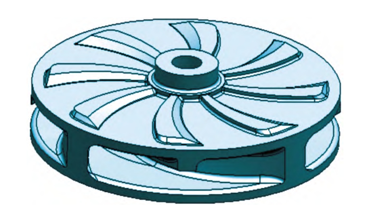
The high chromium cast iron impeller casting has a maximum diameter of 1040mm, a total height of 250mm, a flow channel height of 100mm, a front and rear cover plate thickness of 38mm, four main blades with a thickness of 75mm, and four auxiliary blades on the rear cover plate with a thickness of 45mm. The gross weight of the casting is 730kg. The three-dimensional structure of the impeller casting.
To ensure the hydraulic performance of the impeller and reduce energy loss during the flow process, the inner surface of the flow channel should be smooth and flat, with no protrusions or depressions. The casting structure should be dense, free from defects such as shrinkage, porosity, cracks, and blowholes that affect its performance. A static balance test is required, with an unbalanced mass not exceeding 80g. The impeller casting material is Cr26, a high chromium cast iron with high hardness and good wear resistance. The chemical composition and mechanical properties are shown in Tables 1 and 2, respectively.
Table 1: Chemical Composition of High Chromium Cast Iron Impeller (Mass Fraction, %)
| Element | C | Si | Mn | Cr | Mo | Ni | Cu | S | P |
|---|---|---|---|---|---|---|---|---|---|
| Content | 2.6-2.9 | 0.6-0.8 | 0.6-0.8 | 25-27 | 0.4-0.6 | 0.8-1.0 | 0.8-1.0 | ≤0.06 | ≤0.10 |
Table 2: Mechanical Properties of High Chromium Cast Iron Impeller
| Property | Tensile Strength (Rm/MPa) | Yield Strength (Rp/MPa) | Elongation After Fracture (A/%) | Impact Absorption Energy (Akv/J) | Rockwell Hardness (HRC) |
|---|---|---|---|---|---|
| Specification | ≥400 | ≥500 | ≥8% | ≥30 | 55-62 |
2.2 Initial Casting Process
Dry quartz sand was used as the molding material for the high chromium cast iron impeller casting, and resin-bonded sand was used for the sand core. Based on the structural characteristics and usage requirements of the casting, the parting surface and pouring position were determined. An open pouring system was adopted, with the inner gate set on the rear cover plate of the casting. The cross-sectional areas of each gating unit were determined according to the ratio ΣF直:ΣF横:ΣF内 = 1:(1-1.5):(1-1.5). The advantages of this pouring system include smooth mold filling, reduced cavity erosion, avoidance of turbulence, and reduced metal liquid oxidation.
Four risers were used based on the number of main blades, with two Φ150 open risers (Riser 1) with a height of 450mm and two Φ150 blind risers (Riser 2) with a height of 300mm placed on the opposite side of the pouring system. The risers were positioned on the rear cover plate of the casting and aligned with the main blades. The three-dimensional casting process diagram of the impeller casting.
The metal liquid temperature was controlled between 1450°C and 1480°C before pouring. The vacuum system’s negative pressure value was not less than 0.05 MPa before pouring, and the pouring temperature was controlled between 1380°C and 1400°C. After pouring, the negative pressure value of the vacuum system was maintained at not less than 0.035 MPa for 15 minutes, and the casting could be shaken out after 24 hours.
3. Numerical Simulation of Pouring Process
3.1 Pre-processing of Simulation
A three-dimensional model was constructed using CAD software, saved as an STL file, and imported into simulation software for mesh generation. An appropriate number of mesh elements was selected, with finer mesh division resulting in more accurate calculation results. In this paper, the number of mesh elements for the casting was determined to be 4 million. During the pre-processing stage, the casting material was set as high chromium cast iron Cr26, the mold material was selected as dry quartz sand, the pouring temperature was set to 1400°C, the initial temperature of the sand mold was 20°C, the heat transfer coefficient between the casting and the mold was set to C1200, the heat transfer coefficient between the casting and the air contact surface was set to C400, and the heat transfer coefficient between the mold and the air contact surface was set to C1000. Other parameters were selected from the software defaults.
3.2 Prediction and Analysis of Casting Defects
To verify the feasibility of the casting process and pouring parameters, the simulation software was used to perform simulation and numerical modeling of the above process scheme. Computer simulation revealed that there was a certain risk of porosity near the central shaft head position on the rear cover plate of the casting, as well as within the risers.
Due to the porosity risk, the filling temperature field distribution and solidification process were analyzed based on the simulation results.
3.3 Simulation and Analysis of Filling and Solidification Processes
When the metal liquid passes through the straight and cross gates and directly penetrates the entire inner gate, the metal liquid fills from bottom to top under gravity, with a smooth filling process, no splashing, stable filling speed, and reasonable filling parameters. From the temperature field change and distribution, it can be intuitively seen that during the entire filling process of the casting, the front cover plate part has a lower temperature, the inner gate has a slightly higher temperature, but the position near the central shaft head on the rear cover plate of the casting has a significantly higher temperature than other parts. The metal liquid forms an isolated liquid phase area in this region, which is not fully compensated by the risers, resulting in a certain porosity risk, consistent with the porosity risk area. From the solidification process of the casting, isolated liquid phase areas are also formed at the interface between Risers 1 and 2 and the casting, without forming a clear temperature gradient with other parts, indicating porosity analysis. After analysis and research, the entire filling process of the casting was smooth, and the pouring system designed in this process scheme was reasonable, which was not a factor causing the risk of casting defects.