
Investment casting, also called lost-wax or precision casting, is a net-shape process in which a disposable pattern is coated with refractory slurry, stuccoed, dried, dewaxed, fired, and filled with liquid metal. Its industrial value lies in the combination of fine surface detail, thin sections, complex internal and external geometry, and flexible batch size across a wide range of alloys. Modern investment castings range from a few millimetres to roughly one tonne, with dimensional tolerances commonly in the CT4–CT6 range and down to CT3 for high-precision work; surface roughness can reach about 0.8 µm.
The technique is old but not static. Lost-wax casting is documented in ancient Egypt, India, and China, and Chinese bronze vessels from the Spring and Autumn period show an early mastery of the process. The Second World War created demand for complex, heat-resistant aircraft components such as turbine blades, which pushed investment casting from a craft process into an industrial one. Later developments in binders, refractories, shell making, melting, and directional solidification extended the process to larger, thinner, and more demanding parts.
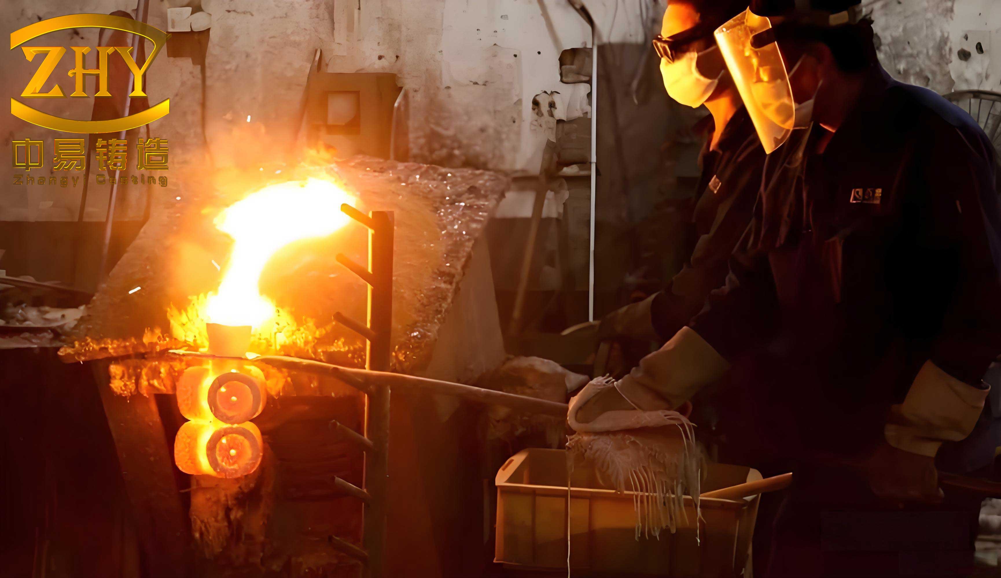
Two digital technologies have changed the economics of the process. First, casting simulation can predict filling, solidification, shrinkage porosity, and thermal stress before a mould is made. Second, additive manufacturing can replace the wax pattern with a polymer pattern, removing the need for wax-injection tooling in low-volume and prototype production. The two technologies address different parts of the same problem: simulation reduces process uncertainty, while rapid patternmaking reduces tooling lead time.
Investment Casting as a Net-Shape Process
The process chain begins with a pattern that closely matches the desired casting, enlarged to compensate for alloy contraction and, when a polymer pattern is used, for pattern shrinkage. Wax is the traditional pattern material, but resin, PLA, and other polymers can also be used. Patterns are assembled onto a runner and gate system, then coated with a refractory slurry. Fine stucco is applied to the face coat, followed by coarser stucco on backup layers. Each layer is dried or chemically set before the next is applied.
After the shell has sufficient green strength, the pattern is removed. Wax is normally melted out in an autoclave or steam vessel; a PLA pattern cannot be melted out in the same way and is removed by thermal decomposition during burnout. The resulting hollow shell is fired to remove residual pattern material, burn out carbonaceous residue, and develop high-temperature strength. Molten metal is then poured into the preheated shell, and the casting is cooled, knocked out, cut from the gating system, cleaned, and heat treated.
The shell is not a passive container. It must provide room-temperature strength for handling, high-temperature strength during pouring, sufficient permeability for gases to escape, controlled thermal expansion, thermal shock resistance, and chemical inertness toward the alloy. These requirements conflict. A dense, strong shell resists cracking but may trap gas; a highly permeable shell may be weaker; a reactive alloy needs a stable face coat. Many casting defects originate at this intersection of shell design, gating design, and solidification behaviour.
Why Filling and Solidification Are Simulated
Casting CAE was introduced as a formal concept at the 50th International Foundry Congress in 1983 by Pehlke and Berry. Since then, commercial finite-element and finite-volume codes have made it routine to simulate mould filling, heat transfer, solidification, and stress. The purpose is not to replace foundry experience but to compare process variants before cutting tooling and to identify where feeding or gas evacuation is likely to fail.
During filling, the alloy is usually treated as an incompressible Newtonian liquid with a free surface. The governing equations are continuity, momentum, and energy conservation. A simplified energy balance for the solidifying system can be written as
$$ \rho c_p \frac{\partial T}{\partial t} = \nabla \cdot (k \nabla T) + Q $$
where \( \rho \) is density, \( c_p \) is specific heat, \( T \) is temperature, \( k \) is thermal conductivity, and \( Q \) includes latent heat release. In the filling stage, the momentum equation also carries the pressure field and viscous terms. Turbulence or surface breakup can entrain oxide films and gas, especially in thin sections where the metal front splits and rejoins.
After filling, solidification is controlled by heat extraction through the shell and by the latent heat released at the solid–liquid interface. Shrinkage porosity appears when a region becomes isolated from liquid feeding before it solidifies. The Niyama criterion is widely used to identify such regions:
$$ \frac{G}{\sqrt{R}} \lt C_{\mathrm{Niyama}} $$
Here \( G \) is the local temperature gradient and \( R \) is the cooling rate. When the ratio falls below a critical value, the local feeding condition is considered insufficient and shrinkage porosity is predicted. The criterion is empirical but useful for comparing gating designs, because it captures both the thermal gradient that drives feeding and the cooling rate that closes the feeding path.
Thermal stress is treated with a thermo-elastoplastic model. The material is elastic below yield and plastic above it, with temperature-dependent elastic modulus and yield strength. Stress concentration at section changes, blade roots, and shell–casting junctions can be compared between designs, although the absolute stress values depend on the assumed interfacial heat-transfer coefficient, constraint conditions, and high-temperature mechanical data.
Gating Design for a Thin-Walled A356 Impeller
A representative case is an A356 aluminium impeller with a shell of 108 mm inner diameter, 112 mm outer diameter, and 2 mm wall thickness. Eight twisted blades are distributed around the shell, with a minimum blade thickness of 1.2 mm. A356, nominally Al–7%Si–0.3%Mg, is used for thin-wall and pressure-tight castings because it combines fluidity, moderate shrinkage, and useful elongation. Its liquidus is about 615 °C and its solidus about 555 °C.
The thin blade sections and the blade-to-shell junctions are the critical regions. A top gating system was first evaluated. Liquid metal entered from the top of the mould and passed downward into the impeller cavity. With pouring at 720 °C, a pouring rate of 0.15 m/s, a shell preheat of 300 °C, and a 4 mm shell, filling was completed in about 5.0 s. The simulation showed an uneven metal front, with turbulence near the centre of the impeller. That flow pattern can entrain oxide films and gas, and it is consistent with the predicted shrinkage cavity in the blade centre, reported as 6.67% on the simulation scale. The maximum effective stress reached 221 MPa at the blade root and shell connection.
A second design used side gating with three gates placed at upper, middle, and lower positions on the shell. The same alloy, pouring temperature, pouring rate, and shell preheat were retained. Filling was smoother and was completed in about 3.72 s. The lower gate filled the lower cavity first, the middle gate joined the rising metal front, and the upper gate completed the fill. The simulated solidification sequence was more directional: the thin blade edges solidified first, the shell and junctions followed, and the gating system remained liquid long enough to feed the casting. Complete solidification was reached at about 729 s, compared with about 409 s for the top-gated case. The longer solidification time is consistent with the gates acting as a feeding reservoir rather than freezing before the casting.
| Indicator | Top gating | Side gating |
|---|---|---|
| Filling behaviour | Uneven front; turbulence near impeller centre | Stable, sequential filling from lower to upper gates |
| Filling completion | About 5.0 s | About 3.72 s |
| Shrinkage prediction | 6.67% shrinkage cavity at blade centre | Maximum shrinkage-porosity index 0.69 at blade–shell junction |
| Maximum effective stress | 221 MPa at blade root and shell junction | 158 MPa at blade root |
| Solidification completion | About 409 s | About 729 s |
| Process assessment | Not selected because of turbulence and stress concentration | Preferred for the casting trial |
The two porosity values were recorded on different scales, so they should be read as a direction of change rather than as a quantitative ratio. The more robust comparison is the combination of flow stability, stress level, and solidification sequence: the side-gated design reduced turbulence, lowered the peak effective stress from 221 MPa to 158 MPa, and moved the last-fed region into the gating system. That is the intended function of a side-gated investment casting system for a thin-walled impeller.
FDM Pattern Substitution and Shell Practice
Fused deposition modelling was used to produce a PLA pattern of the impeller. The printer was a Kossel-type delta machine, an open-source design that maps Cartesian motion onto three vertical carriages. The machine used a remote extruder, a heated effector with dual cooling fans, and a glass build plate backed by a silicone heater held at 60 °C. The dual-fan arrangement reduces turbulence at the nozzle and accelerates layer cooling, which improves surface finish and dimensional stability in thin sections.
The filament was 1.75 mm PLA, a thermoplastic polyester derived from lactic acid. The pattern material had a nominal melting point near 200 °C, a stated shrinkage of 0.5%, a tensile strength of 40–60 MPa, and an ash content of 0.03%. The low ash content is important because any residue left after burnout can react with the shell or remain in the mould cavity. The impeller body was printed at 100% infill to give the thin blades internal support, while the supports were printed at 30% infill to reduce material use and make removal easier.
| Parameter | Value |
|---|---|
| Pattern material | PLA, 1.75 mm filament |
| Nozzle diameter | 0.4 mm |
| Layer height | 0.2 mm |
| Perimeters | 3 |
| Infill | 100% in impeller; 30% in supports |
| Infill pattern | Rectilinear |
| Print speed | 70 mm/s |
| Build plate temperature | 60 °C |
| Supports | 20 × 20 × 14 mm blocks below each blade |
| Scale factor | 1.013 |
| Build time | About 2 h |
| Dimensional accuracy | About 0.2 mm |
The pattern was scaled by a factor of 1.013 to compensate for combined contraction. In the case calculation, A356 contraction of 0.67%, PLA shrinkage of 0.5%, and a shell-expansion term were combined into a net scale factor. The impeller was printed with its supports, removed from the build plate, cleaned, and bonded to a wax runner system. The wax runner provides the conventional gating geometry and a compatible surface for the shell build.
The shell was produced with a four-layer colloidal silica process. A GRJ-30 silica sol was used as the binder. The face coat contained fused silica, which provides a stable, smooth surface in contact with the alloy. Backup layers used coal-gangue powder, a lower-cost refractory that develops adequate strength and permeability. The face layer was dried without forced air to avoid skinning and cracking; backup layers were dried with controlled air movement. The drying schedule was kept at 22–25 °C with staged humidity, because rapid drying of a green shell can produce differential shrinkage and surface cracks.
| Layer | Slurry | Refractory powder | Viscosity (s) | Slurry density (g/cm³) | Stucco (mesh) | Drying condition |
|---|---|---|---|---|---|---|
| Face | Silica sol | Fused silica | 55–65 | 2.1–2.3 | 100/120 | 22–25 °C, 60–70% RH, no forced air, 6–8 h |
| Transition | Silica sol | Coal-gangue powder | 20–25 | 1.8–2.0 | 30/60 | 22–25 °C, 50–60% RH, 6–8 m/s air, ≥8 h |
| Reinforcement | Silica sol | Coal-gangue powder | 25–35 | 2.1–2.3 | 16/30 | 22–25 °C, 40–60% RH, 6–8 m/s air, ≥12 h |
| Seal | Silica sol | Coal-gangue powder | 25–35 | 1.8–2.0 | None | 22–25 °C, 40–60% RH, 6–8 m/s air, ≥24 h |
Dewaxing, Burnout, Casting, and Heat Treatment
Because the PLA impeller was bonded to a wax runner, the assembly was first dewaxed in an autoclave at 0.7 MPa and 150 °C for 5 min. The wax melted and drained, leaving the PLA impeller inside the shell. The shell was then fired. The burnout schedule was slow heating to 250 °C with a 1 h hold, followed by 400 °C for 1 h and a final rise to 880–920 °C for 1 h. The shell was cooled below 100 °C before handling.
The 250 °C hold is the critical stage for PLA removal. PLA decomposes in the range of about 230–260 °C, depending on crystallinity, into carbon monoxide, carbon dioxide, water, and acetaldehyde, together with other volatile fragments. The pattern does not melt out as a liquid; it softens, expands, and then decomposes. If the heating rate is too fast or the shell permeability is too low, the internal pressure can crack the green shell before the volatiles escape. A slow ramp, a permeable backup layer, and a vented shell design are therefore more important for PLA patterns than for wax patterns.
The A356 melt was refined with hexachloroethane at 0.3% of the charge weight. The refining temperature was 750 °C, with three additions of 3 min each and a total refining time below 15 min. The melt was then held for about 10 min to allow gas and inclusions to separate. A chloride–fluoride modifier was added at 2–2.5% of the charge weight at 710–750 °C for 10–15 min to refine the eutectic silicon and improve mechanical properties. The shell was preheated to 400 °C for 1 h before gravity pouring at 720 °C.
After casting, the impeller was cooled, knocked out, cut from the runner, cleaned, and heat treated to T6 condition. The solution treatment was 535 ± 5 °C for 6–18 h, followed by water quenching at 70–100 °C with a maximum transfer time of 15 s. Aging was performed at 155 ± 5 °C for 6–10 h in air. The trial casting was reported to fill completely, reproduce the blade contours, and show good surface quality after T6 treatment and machining, with no obvious surface-connected shrinkage defects.
One boundary condition deserves attention: the simulation used a shell preheat of 300 °C, while the casting trial preheated the shell to 400 °C. The higher preheat reduces the thermal gradient and can change filling and feeding behaviour. The trial therefore supports the general workflow and the feasibility of the PLA pattern, but it does not constitute an exact validation of the 300 °C simulation boundary condition.
What the Case Establishes and What It Does Not
The case supports three practical conclusions. First, gating position matters more than a single global pouring parameter for a thin-walled impeller. The side-gated design changed the filling front, reduced turbulence, lowered the peak effective stress, and provided a feeding path through the runner. Second, a PLA pattern produced by FDM can survive shell making and be removed by thermal decomposition, leaving a cavity suitable for gravity casting. Third, a 1.013 scale factor and a 0.2 mm FDM accuracy are adequate for a trial impeller when the critical dimensions are checked and the pattern is supported during printing.
The case does not establish production qualification. It covers one alloy, one impeller geometry, and a limited number of trials. The reported casting quality is based on visual and dimensional assessment after heat treatment and machining, not on a statistically sampled X-ray or CT porosity audit. FDM also introduces stair-step surfaces, layer bonding anisotropy, and a dimensional uncertainty of about 0.2 mm, which is significant for thin blade sections and small fillets. PLA burnout leaves a small ash residue and generates volatile organic compounds; shell permeability, heating rate, and ventilation must be controlled to avoid shell cracking and residual carbon.
For industrial adoption, the pattern-to-casting chain would need tighter control of filament moisture, build reproducibility, ash content, shell face-coat reactivity, and burnout atmosphere. Casting qualification would require X-ray or CT inspection, sectioning at the blade root, tensile testing of test bars, and dimensional layout of the final machined part. These are standard qualification steps, not evidence that the process has already met them.
Industrial Relevance
Investment casting remains a major precision-manufacturing route. In 2013, global precision-casting output was valued at about US$12.2 billion. The reported regional split was approximately 41% for North America, 23% for mainland China, 22% for Europe, and 12% for Japan, Korea, and other regions. North America and Europe remain strong in aerospace and gas-turbine castings, where high-value components justify tight process control. Large-aircraft programmes such as the Boeing 787 and Airbus A350 support demand for complex, high-integrity castings.
Additive manufacturing provides a complementary path for low-volume production. The additive manufacturing market was about US$5.1 billion in 2015, with a three-year compound annual growth rate of 33%. For investment casting, the most practical near-term application is not mass production of simple parts, but prototypes, spare parts, custom impellers, and geometries for which wax-injection tooling would be expensive or slow to modify. FDM is attractive because the equipment is low-cost, PLA is widely available, and the pattern can be burned out in a conventional shell system.
The economic mechanism is straightforward: simulation reduces the number of casting trials, and rapid patternmaking removes the wax tooling step from the first iteration. The technical mechanism is more demanding: the pattern must be dimensionally compensated, the shell must survive polymer decomposition, and the gating system must feed the last-solidifying sections. When these conditions are met, simulation-guided investment casting with FDM patterns becomes a useful bridge between digital design and a sound metal component, particularly for complex parts at low to moderate volume.