1. Test purpose
(1) The random characteristics of typical casting defects distribution of cast steel joints are analyzed;
(2) Verify the accuracy of ultrasonic flaw detection;
(3) It provides a verification basis for the casting simulation in Chapter 4.
2. Test instrument
The cutting equipment used for slicing test is sawing machine and water knife.
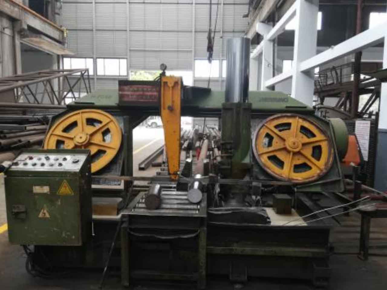
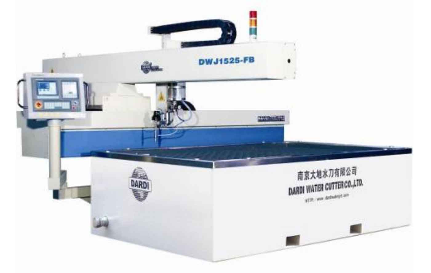
The sawing machine is h-7056 large band sawing machine (see Figure 1), which adopts oil pressure tensioning and frequency conversion speed regulation; The water cutter is dwj1525fb three-axis cantilever water cutter (see Figure 2), with cutting accuracy of ± 0.10mm and maximum water pressure of 350Mpa.
3. Cutting scheme of slice test
Due to the large size of cast steel joints, conventional CT scanning and other technical means can not be used to detect the casting defects of the whole joint, so a more intuitive sectioning test method is adopted. As for the overall slice analysis of cast steel joints, at present, only a. Ma mentioned the mechanical slice test of cast steel joints, but the number of slices in this literature is small.
By analyzing the NDT test results of joints, it is preliminarily determined that the location of stiffener, the location near branch pipe and the location near riser are the concentrated location of casting defects. Therefore, the principle of determining the cutting scheme is as follows: first cut the main pipe into rings along the transverse direction, and then cut the branch pipe into irregular sections along the transverse direction of the main pipe; Then, the main ring section is cut circumferentially, and the section layout principle is: the accumulation area of casting defects is dense, and the dispersion area of casting defects is sparse.
The specific section distribution rules are as follows:
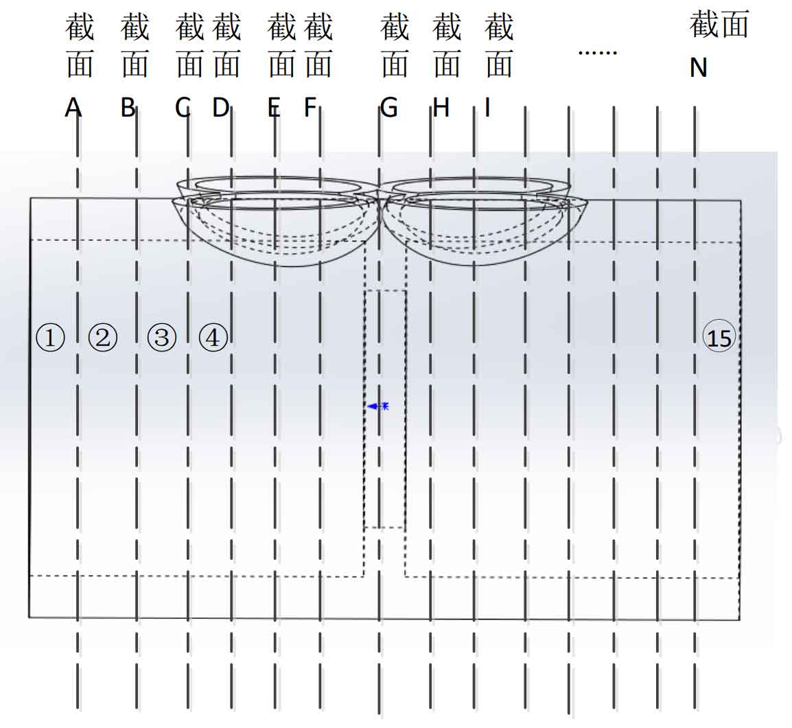
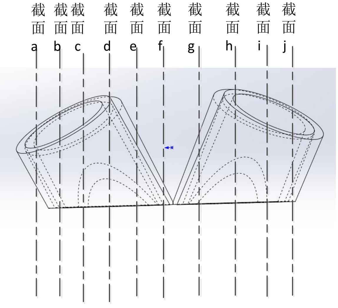
(1) Cut the main pipe of the test node into 15 rings, and each ring is marked as ①, ②, ③, ④ 15. Each section is called the main pipe large section, which is successively marked as a, B, C N; The branch pipe is cut into 11 pieces, and each section is called the large section of the branch pipe, which is successively recorded as sections a, B, C j。 See Fig. 3 and Fig. 4 for cutting position;
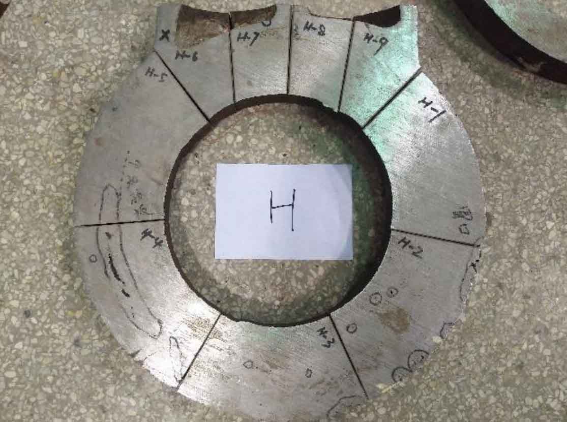
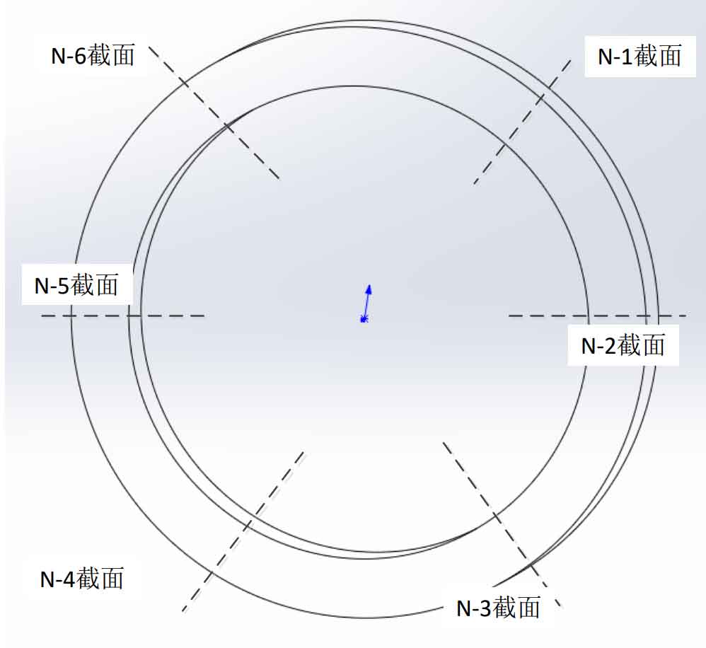
(2) Cut the ring obtained after cutting the main pipe into 6 pieces. The cutting position is shown in Figure 5. Each piece is marked as n-1, n-2, n-3, N-6, where n is the number of rings;
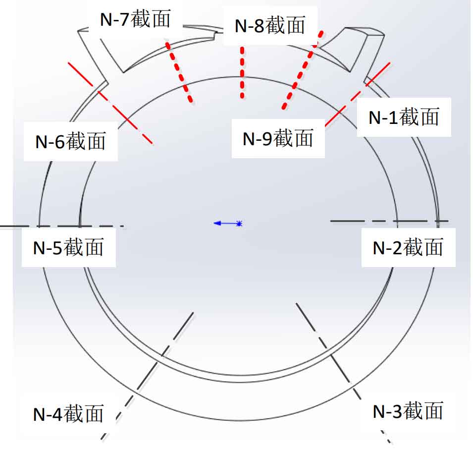
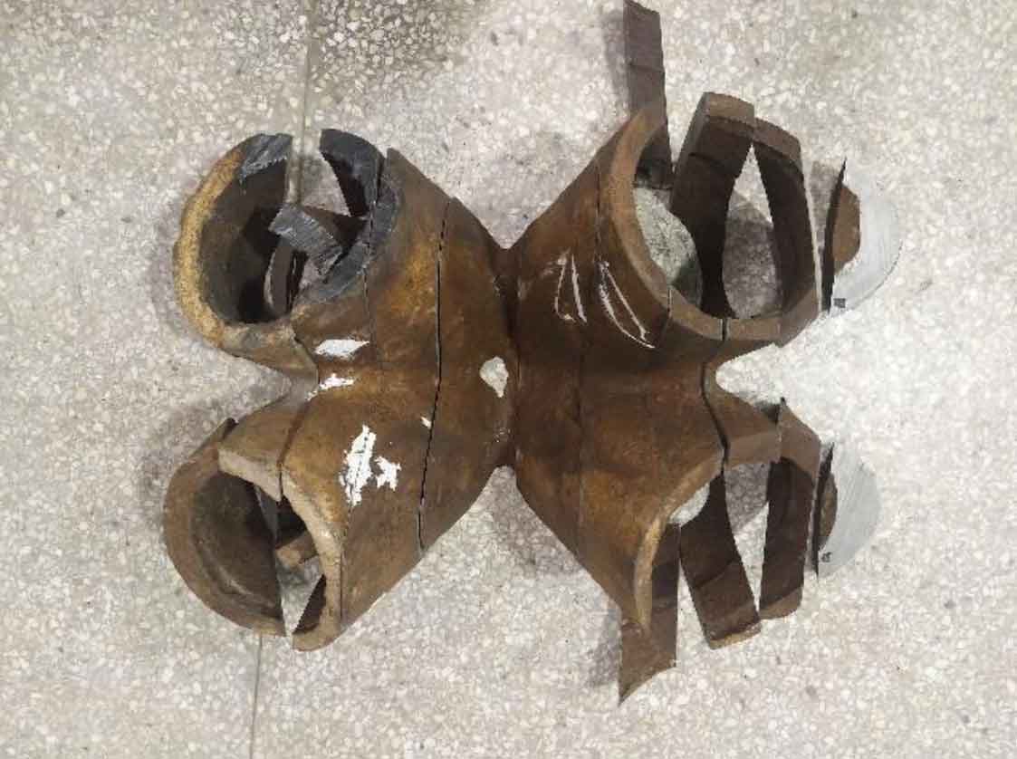
(3) The connecting part between the branch pipe and the main pipe is divided into four pieces. The cutting position is shown in Figure 6.
To sum up, there are 144 sections of the whole node.
4. Specimen slicing
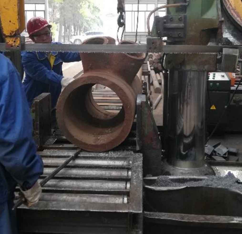
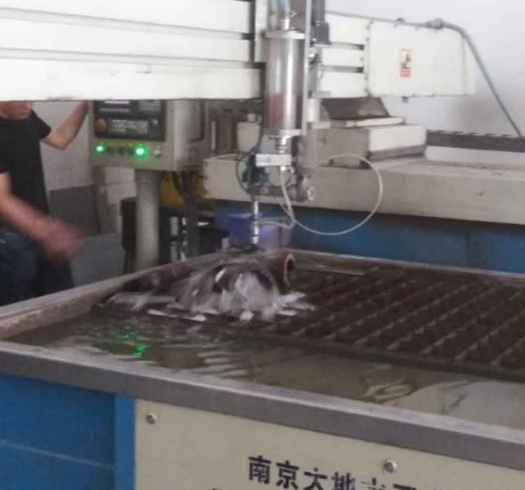
Due to the height limitation of the saw, flame cutting is used to cut off a corner of the branch pipe in the cutting process, so that the saw blade can fall to the bottom, and then cut a main pipe ring to facilitate the cutting of the branch pipe. The cutting spacing is 50 ~ 80mm, and each knife is cut for 2 hours, and focus on the parts with casting defects detected by ultrasonic testing. See Fig. 7 and Fig. 8 for band sawing machine and water jet cutting. See Fig. 9, FIG. 10 and FIG. 11 respectively for the main pipe of cast steel joint after cutting into a ring and the main pipe and branch pipe further cut into slices.
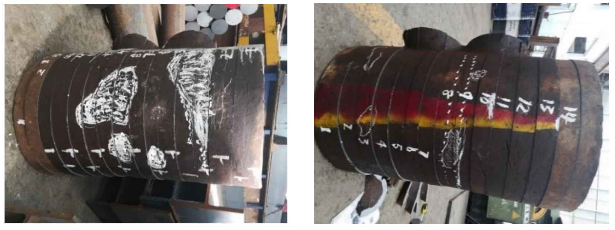
The white dotted line shown in Fig. 9b is the position of the internal stiffener. The position considered to have casting defects after ultrasonic nondestructive testing has been marked with a white pen for comparison with the internal casting defects found after slice flaw detection.