
In my extensive work with nodular cast iron, I have consistently encountered the challenge of volumetric defects, specifically shrinkage cavities and porosity. These defects are among the most common causes of scrap in foundries, severely compromising the mechanical integrity of castings and potentially leading to catastrophic failures. The solidification behavior of nodular cast iron is uniquely complex, distinguished by a mushy or pasty solidification mode over a broad temperature range. This characteristic fundamentally differentiates it from other casting alloys like steel or gray iron and is the primary root cause of shrinkage-related issues. A deep understanding of the intricate volume changes during solidification is therefore not merely academic; it is a practical necessity for designing robust casting processes that yield sound, high-quality components. This article, drawn from my professional experience and research, delves into the solidification dynamics of nodular cast iron and explores strategic process adaptations to mitigate shrinkage defects.
The journey of molten nodular cast iron from pouring to complete solidification is a dynamic saga of competing volumetric changes. Unlike most metals that undergo monotonic contraction, nodular cast iron experiences a complex interplay of three distinct shrinkage phases and one expansion phase. This can be conceptualized as a sequence: liquid contraction, initial graphitization expansion, solidification (eutectic) contraction, eutectic expansion, and finally, solid-state contraction. The final soundness of a casting is the net result of these superimposed effects, heavily influenced by chemical composition, cooling rates, and mold rigidity.
The first stage, liquid contraction, begins immediately upon pouring. As the temperature drops from the pouring temperature ($T_{pour}$) down to the liquidus temperature ($T_{liq}$), the atomic kinetic energy within the melt decreases, leading to a reduction in interatomic spacing and a macroscopic decrease in volume. This contraction manifests as a drop in the liquid metal level in the pouring basin or sprue. The volume of liquid shrinkage can be quantified using the following fundamental relation:
$$\Delta V_{SL} = \alpha_{SL} (T_t – T_{t+\Delta t}) V_0$$
where $\Delta V_{SL}$ is the volume of liquid shrinkage over a time interval $\Delta t$, $\alpha_{SL}$ is the coefficient of liquid volumetric shrinkage for the specific alloy, $T_t$ and $T_{t+\Delta t}$ are the temperatures at the beginning and end of the interval, and $V_0$ is the initial volume. For typical nodular cast iron compositions, the liquid contraction approximates 1.5% for every 100°C temperature drop. The total liquid contraction is therefore highly dependent on the chosen pouring temperature, as illustrated in the table below.
| Pouring Temperature (°C) | 1450 | 1400 | 1350 | 1300 |
|---|---|---|---|---|
| Approximate Liquid Contraction (%) | 4.50 | 3.75 | 3.00 | 2.25 |
This table underscores a critical practical insight: lowering the pouring temperature, within the limits of avoiding mistruns, directly reduces the initial liquid shrinkage volume, thereby lessening the total volumetric deficit that must be compensated for later.
As the temperature falls below the liquidus for hypereutectic compositions ($C_E > C_{E0}$), the initial graphitization expansion phase commences. Primary graphite nodules begin to precipitate directly from the melt. The growth of these graphite particles, which have a much lower density (approximately 2.25 g/cm³) than the iron melt, causes a volumetric expansion. The amount of primary graphite ($G_{initial}$) that precipitates can be estimated by:
$$G_{\text{initial}} = \frac{C_X – C_{C}}{100 – C_{C}} \times 100\%$$
where $C_X$ is the total carbon content of the iron and $C_{C}$ is the carbon content at the eutectic point. The associated volume expansion is significant, with every 1% of graphite precipitated causing an expansion ranging from 2.05% to 3.4%. This expansion can partially offset the preceding liquid contraction. However, in heavy-section castings with slow cooling, these primary graphite nodules have sufficient time to float upwards, leading to the well-known defect of graphite flotation in the upper regions of the casting. Controlling carbon equivalent (CE) and enhancing cooling rates in thick sections are key strategies to prevent this.
The core of the solidification drama unfolds during the eutectic reaction. This is where the characteristic mushy solidification of nodular cast iron becomes most apparent. The remaining liquid simultaneously transforms into austenite and graphite. The crystallization of austenite, a dense, face-centered cubic structure, involves a substantial contraction—typically estimated at around 3.5% volumetric shrinkage. Concurrently, the precipitation and growth of the spherical graphite nodules from the eutectic liquid generate a powerful eutectic expansion. This expansion is the most pronounced of the entire process and is the cornerstone of many advanced feeding techniques for nodular cast iron. The net volume change during this critical phase depends on the balance between the contraction from austenite formation and the expansion from graphite formation. This balance is influenced by factors like inoculation efficacy, cooling rate, and the mold’s ability to resist deformation.
Finally, after complete solidification, the casting undergoes solid-state contraction as it cools from the solidus temperature to room temperature. This phase is more predictable and linear, governed by the solid thermal contraction coefficient.
The overall volume change ($\Delta V_{total}$) from pouring to room temperature is the summation of all these sequential and overlapping effects:
$$\Delta V_{\text{total}} = \sum \Delta V_{\text{liquid}} + \sum \Delta V_{\text{initial graph.}} + \sum \Delta V_{\text{eutectic contr.}} + \sum \Delta V_{\text{eutectic exp.}} + \sum \Delta V_{\text{solid}}$$
Understanding this equation is paramount for the foundry engineer. It moves the design of gates, risers, and cooling systems from a rule-of-thumb practice to a science-based optimization problem.
The mushy solidification, where a coherent solid skeleton (austenite dendrites with encapsulated graphite) forms while significant liquid remains, is the direct reason why nodular cast iron is prone to dispersed microshrinkage or porosity. The interdendritic channels become blocked, preventing liquid metal from flowing to compensate for shrinkage in isolated pockets. The variety of shrinkage defects encountered is broad, as cataloged in the following table based on my observations.
| Category | Defect Type | Typical Location & Characteristics |
|---|---|---|
| Exposed Shrinkage | Shrinkage at Gate | Occurs at or near the gate connection, often due to premature solidification of the gate. |
| Shrinkage at Vent/Overflow | Appears at the highest points or vent openings where liquid feed is last. | |
| Sponge-Like Shrinkage | A network of surface-connected porosity, often in heavy sections. | |
| Leakage Porosity | Interconnected porosity leading to pressure tightness failure. | |
| Internal Shrinkage | Shrinkage at Corners & Junctions | Forms in thermal hotspots where geometry promotes localized slow cooling. |
| Axial Line Shrinkage | Occurs along the centerline of cylindrical or plate-like sections. | |
| Dispersed Microshrinkage | Widely scattered microscopic pores, a hallmark of mushy solidification. |
To combat these defects, the casting process must be strategically designed to harness the beneficial eutectic expansion and minimize the detrimental effects of shrinkage. The first line of defense is melt quality and chemistry control. A carbon equivalent in the range of 4.3% to 4.4% is generally optimal, providing sufficient graphite for expansion while avoiding excessive primary graphite. A higher carbon-to-silicon ratio is often beneficial in reducing shrinkage tendency. Furthermore, precise control of alloying elements (like copper, tin) and residual magnesium levels is critical, as they influence the morphology and kinetics of austenite and graphite formation.
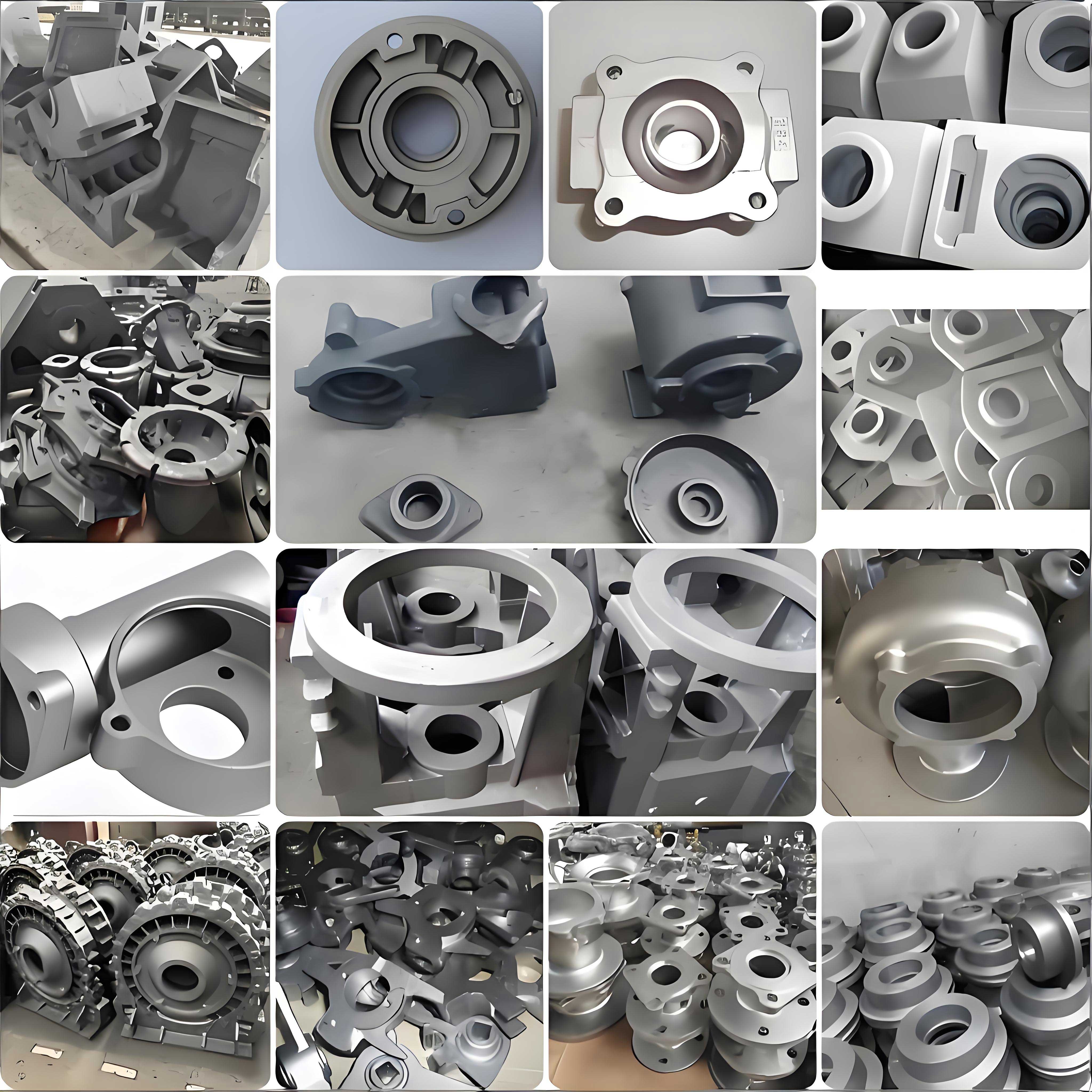
The image above illustrates a typical sound nodular cast iron component, the quality of which is a direct result of controlled solidification. Achieving this requires meticulous attention to mold rigidity. This is perhaps the most critical factor in implementing riserless or minimal-riser casting for nodular cast iron. During the eutectic expansion phase, if the mold walls are sufficiently rigid and non-yielding, the expansive pressure generated internally is directed inwards, effectively performing “self-feeding” and compensating for shrinkage in remote parts of the casting. Techniques to enhance mold stiffness in green sand molding include the use of strong molding sands, incorporating chills (metal or graphite), or placing reinforcing materials like耐火砖 within the mold. The modulus (volume-to-surface-area ratio) of the casting is also crucial; a general rule suggests that a modulus greater than 2.5 cm is a prerequisite for successful riserless casting of nodular cast iron, as it ensures a favorable thermal gradient.
The design of the gating and feeding system must be radically rethought for nodular cast iron compared to steel. Due to the significant eutectic expansion, conventional thick gates and riser necks become liabilities. If they remain open (liquid) during the expansion phase, the expanding metal can be forced back into the gating system, leaving the casting itself unsupplied and creating shrinkage. Therefore, gating design emphasizes thin, quickly freezing sections. Ingress gates are often designed as thin plates with an aspect ratio (length-to-width) greater than 3 to ensure rapid solidification after filling. Similarly, riser necks must be carefully sized to freeze before the onset of major eutectic expansion in the casting, isolating the riser and preventing back-flow. This concept is known as a “neck-off” riser. The modulus of the riser neck ($M_n$) must be carefully calculated to solidify at the right time relative to the casting modulus ($M_c$). A common approach is to ensure $M_n < k \cdot M_c$, where $k$ is a factor less than 1, dependent on the specific alloy and cooling conditions.
Mathematical modeling and simulation have become indispensable tools in my work for predicting these complex interactions. Solidification simulation software uses numerical methods to solve the heat transfer equations coupled with models for the volume changes described. The governing heat transfer equation during solidification is:
$$\rho c_p \frac{\partial T}{\partial t} = \nabla \cdot (k \nabla T) + \rho L \frac{\partial f_s}{\partial t}$$
where $\rho$ is density, $c_p$ is specific heat, $T$ is temperature, $t$ is time, $k$ is thermal conductivity, $L$ is latent heat, and $f_s$ is the solid fraction. The source term involving latent heat and solid fraction rate is intricately linked to the volume change models for nodular cast iron. Advanced simulations can predict shrinkage propensity by tracking the pressure drop in the interdendritic liquid or using criteria functions like the Niyama criterion, adapted for the expansion characteristics of nodular cast iron.
Beyond these core principles, numerous secondary factors play a role. Inoculation practice is vital for promoting a large number of small, uniformly distributed graphite nodules. A fine graphite structure leads to a more uniform and earlier onset of eutectic expansion, improving feeding efficiency. The type and amount of inoculant (e.g., FeSi alloys containing Ca, Ba, Al) must be optimized for the section size and base iron composition.
Pouring time and rate also influence temperature distribution and thermal gradients. A very slow pour might lead to excessive cooling in thin sections before thicker sections are filled, while a turbulent fast pour can cause dross formation. An optimized pouring system minimizes turbulence, promotes sequential filling from the bottom up, and establishes a favorable temperature gradient for directional solidification towards the risers or the gate, if designed as a feeding channel.
The use of chills is a powerful method to manipulate local solidification patterns. By placing a material of high thermal conductivity (like iron, copper, or graphite) adjacent to a casting hotspot, the local cooling rate is dramatically increased. This can shift the solidification mode from mushy to more directional, helping to move the shrinkage-prone zone to a location where it can be fed by a riser or into an expendable part of the casting, such as a feeder head or a sacrificial pad.
To summarize the key process control parameters for minimizing shrinkage in nodular cast iron, consider the following comprehensive table:
| Process Parameter | Target / Recommended Practice | Primary Effect on Solidification |
|---|---|---|
| Carbon Equivalent (CE) | ~4.3 – 4.4%; C/Si ratio > 1 | Balances graphitization potential (expansion) with fluidity and shrinkage tendency. |
| Pouring Temperature | As low as possible without mistruns (e.g., 1300-1350°C) | Minimizes liquid contraction volume. |
| Inoculation | Effective, late-stream inoculation | Increases graphite nodule count, promotes uniform and early eutectic expansion. |
| Mold Rigidity | High strength sand, use of chills/reinforcements | Contains eutectic expansion pressure, enabling self-feeding and riserless designs. |
| Gating Design | Thin, choke-shaped gates; rapid fill with minimal turbulence | Ensures gates freeze quickly to prevent metal back-flow during expansion. |
| Riser Design | Neck-off risers with calculated modulus; possibly riserless for high-modulus castings | Provides feed metal during contraction phases but isolates before expansion back-flow. |
| Cooling Rate Control | Strategic use of chills and cooling fins | Creates directional solidification, moves shrinkage to feedable locations. |
| Simulation | Mandatory for complex castings | Predicts shrinkage locations, thermal gradients, and optimizes process parameters virtually. |
In conclusion, mastering the production of sound nodular cast iron castings is an exercise in managing contradictions—harnessing expansion to counter contraction. The糊状凝固 (pasty solidification) nature of nodular cast iron is not an insurmountable obstacle but a defining characteristic that must be respected and utilized. By deeply understanding the sequential volume changes—liquid shrinkage, graphite expansion, austenite contraction, and eutectic expansion—the foundry engineer can design processes that actively promote soundness. This involves a synergistic approach: controlling melt chemistry to optimize the expansion potential, designing rigid molds to contain that expansion, and engineering gating and feeding systems that synchronize with the precise timing of these volumetric events. Through this integrated understanding, the incidence of shrinkage cavities and porosity in nodular cast iron can be dramatically reduced, leading to higher yield, improved mechanical properties, and greater reliability in demanding applications. The journey from molten metal to a robust nodular cast iron component is a testament to the intricate balance between material science and practical engineering, a balance I have dedicated my career to achieving.