
The production of high-integrity cylinder heads for diesel engines represents one of the most demanding challenges in the foundry industry. As a critical component, the cylinder head must withstand extreme thermal and mechanical stresses while maintaining perfect sealing against combustion gases and coolant. The consequences of casting defects in such a part are severe, leading directly to engine failure, costly scrap, and significant financial loss. In our production facility, the journey with the Model 226B cylinder head, a component for a technically advanced diesel engine developed through an international partnership, became a defining case study in systematically identifying, analyzing, and ultimately solving persistent casting defects. The initial scrap rate, hovering around 10%, was economically unsustainable, especially given the high alloy content of the iron. This narrative details our first-hand experience in tackling these problems.
The specified material for the 226B cylinder head is a high-grade alloyed gray iron, GG30Cu. Achieving the required microstructure and mechanical properties—particularly high strength, good thermal conductivity, and excellent pressure tightness—demands precise control over the chemical composition and thermal conditions during pouring. The target chemical ranges are summarized in the table below.
| Element | Target Range (%) | Primary Function |
|---|---|---|
| Carbon (C) | 3.35 – 3.45 | Graphite formation, fluidity |
| Silicon (Si) | 1.9 – 2.1 | Graphitizer, strengthens ferrite |
| Manganese (Mn) | 0.7 – 0.9 | Counteracts sulfur, strengthens pearlite |
| Copper (Cu) | 0.8 – 1.0 | Refines pearlite, improves strength & corrosion resistance |
| Chromium (Cr) | 0.2 – 0.3 | Carbide stabilizer, increases hardness and strength |
| Molybdenum (Mo) | 0.3 – 0.4 | Enhances high-temperature strength and fatigue resistance |
| Sulfur (S) | ≤ 0.10 | (Impurity – kept low) |
| Phosphorus (P) | ≤ 0.10 | (Impurity – kept low) |
The pouring temperature was identified as a critical process parameter very early on. For a thin-walled casting like this, where internal walls can be as thin as 4 mm, low superheat dramatically increases the risk of mistruns and cold shuts. Our empirical data established a clear correlation. The fluidity length L of the iron can be conceptually related to temperature by an equation of the form:
$$ L = k \cdot (T_{pour} – T_{liquidus})^n $$
where \( k \) and \( n \) are constants dependent on the alloy and mold conditions, \( T_{pour} \) is the pouring temperature, and \( T_{liquidus} \) is the liquidus temperature. Operating below 1400°C resulted in a steep increase in defect-related scrap. Therefore, we strictly controlled the pouring temperature within the optimal window of 1400°C to 1420°C.
The original production process utilized a high-pressure molding line. The mold was configured for four castings per box. The core assembly was complex, involving nine cores for every two castings. These included a large main outer core (cold-box), and pairs of upper/lower water jacket cores, intake runner cores, and exhaust runner cores (mostly hot-box). The assembled core package was dipped in a refractory coating and oven-dried. The gating system was an open-type, single-side design with the sprue located at the parting line. The upper mold half was made of green sand, and extensive venting was provided via core prints and multiple riser vents (acting as exhaust sticks) placed directly on the casting cavity itself.
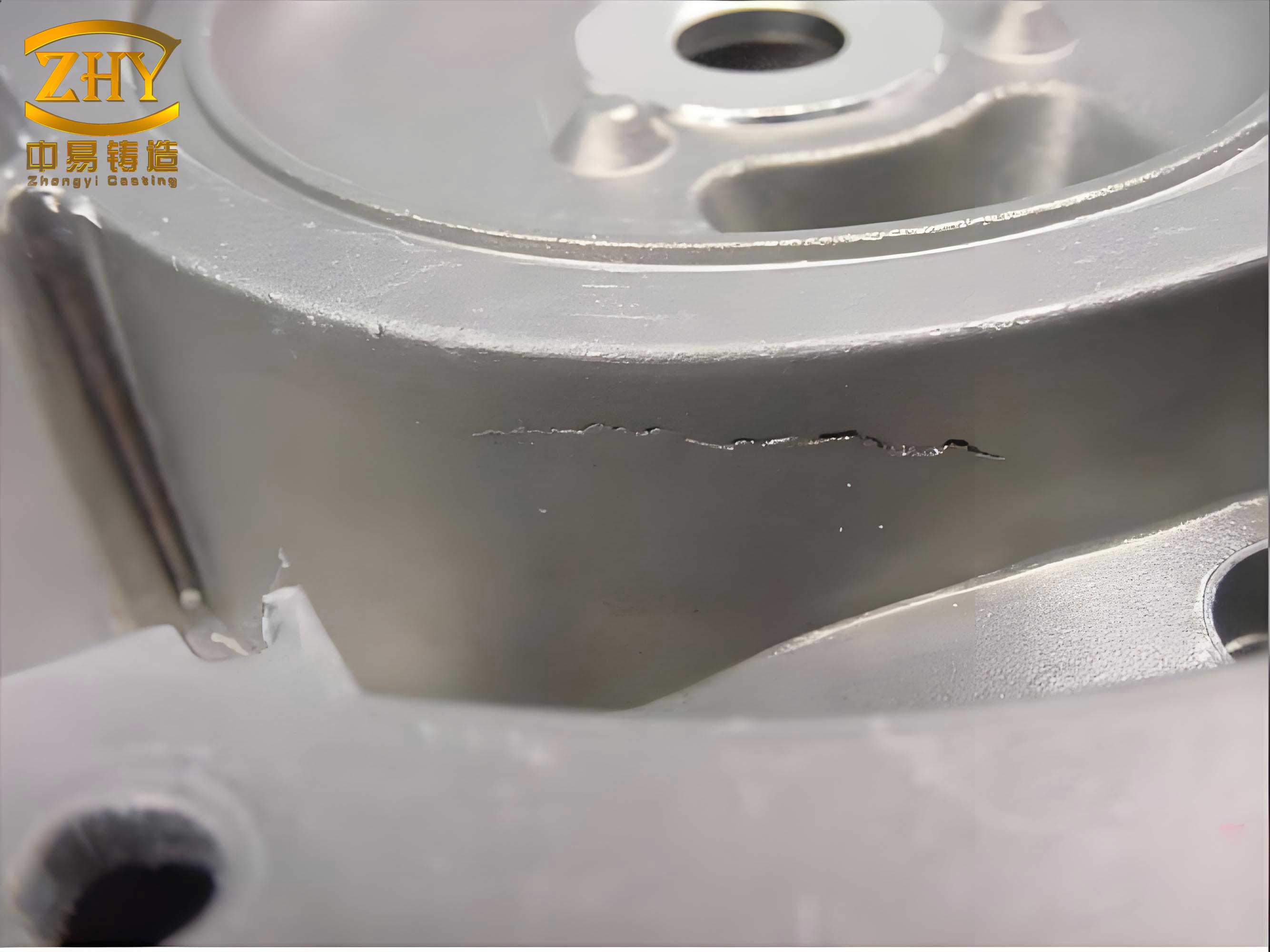
Despite this sophisticated, imported tooling and process, we faced a persistent and dominant casting defect: gas porosity. This single flaw accounted for a staggering 90% of the total scrap loss for the 226B cylinder head. The casting defects manifested in a very specific location: at the junction where the exhaust vent stick met the casting body, particularly on the side of the head opposite the main工艺孔 (process hole). The characteristic appearance was a subsurface blowhole or pinhole cluster visible after the vent stick was removed.
A thorough root-cause analysis was conducted. The problem was fundamentally one of gas evolution and venting dynamics. During pouring, the majority of the core assembly becomes entirely encapsulated by molten iron. The cores, especially the hot-box varieties, generate large volumes of gas from the thermal decomposition of binders. This gas must escape through the core prints and, critically, through the molten metal itself before solidification seals the paths.
The physics can be partly described by considering the pressure balance at the gas/liquid metal interface. For a gas bubble to nucleate and grow within the liquid, the internal gas pressure \( P_{gas} \) must overcome the sum of the ambient pressure \( P_{atm} \), the metallostatic pressure \( \rho g h \), and the capillary pressure due to surface tension \( \frac{2\sigma}{r} \), where \( \sigma \) is the surface tension and \( r \) is the bubble radius.
$$ P_{gas} \geq P_{atm} + \rho g h + \frac{2\sigma}{r} $$
In our thin-walled, compact geometry, the available paths for gas to travel to the nearest vent (the exhaust sticks) were long and restricted. The local solidification time \( t_f \) for a thin section, approximated by Chvorinov’s Rule as \( t_f = k \cdot (V/A)^2 \), is very short. Essentially, the metal in these critical junctions froze before all the entrapped core gas could escape to the vents. The gas, supersaturated in the solidifying iron, precipitated at the last point to solidify—the thermal junction at the base of the exhaust vent stick—creating the characteristic porosity defect. Other, less frequent but still costly casting defects included: sand inclusions caused by core crush during mold closing; internal fins or “flash” in the water jacket caused by molten iron penetrating gaps in the bonded core assembly; and core breakage due to the buoyant forces of the liquid iron.
Faced with these compounding casting defects, a fundamental process modification was necessary. The solution was the introduction of a new “top cover” core. This was not a minor adjustment but a significant redesign of the tooling and process flow. The new core, produced two per box on a separate core shooter, would sit atop the main outer core, effectively creating a secondary upper mold cavity. This design had multiple synergistic benefits, as outlined in the comparison table below.
| Aspect | Original Process | Modified Process (With Top Cover Core) |
|---|---|---|
| Core Assembly | Main outer core + internal cores. | Main outer core + top cover core (pre-assembled) + internal cores. |
| Upper Mold | Conventional green sand cope. | Green sand cope now interfaces with the precisely shaped top cover core. |
| Venting Path | Gas must travel laterally through thin walls to exhaust sticks on casting. | Provides direct, short vertical venting channels through the top cover core to the cope. |
| Thermal Management | Hot spot at exhaust stick junction. | Small insulating riser/sleeve placed over exhaust stick location, moving thermal center upward and delaying solidification at critical point. |
| Mechanical Protection | Cores exposed during closing, risk of sand crush. | Top cover core protects underlying core assembly from direct sand impact during mold closing. |
| Dimensional Control | Parting line flash on top face of casting. | Top face is now formed by core-to-core joint, yielding a cleaner, more precise surface. |
The introduction of the top cover core directly attacked the root cause of the gas porosity. By providing dedicated, low-resistance venting channels, it reduced the back-pressure \( P_{gas} \) building up in the core assembly. The addition of the small insulating riser altered the solidification sequence, effectively extending the local solidification time \( t_f \) at the critical junction. This gave the entrapped gases more time to evacuate, preventing supersaturation and bubble formation. The result was the near-complete elimination of this dominant casting defect.
Simultaneously, we addressed the secondary casting defects. The issue of internal fins in the water jacket was traced to the failure of the commercial water-glass-based core adhesive under intense heat near the ingate. The adhesive would melt and decompose prematurely, allowing metal penetration. Our team developed a proprietary, high-temperature-resistant adhesive formulation. Through iterative testing, we optimized its viscosity, bonding strength, and thermal stability. The performance of the new adhesive can be conceptualized by its ability to maintain bonding strength \( \tau_b \) above a critical threshold at elevated temperatures \( T \) experienced near the ingate:
$$ \tau_b(T) \geq \rho g h_{metal} \cdot A_{gap} \quad \text{for } T \leq T_{decomposition} $$
This ensured the core joints remained sealed throughout the filling and initial solidification phase, drastically reducing internal flash.
Finally, we reinforced strict procedural discipline in the molding department. Operators were trained to meticulously clear all vent holes in the cope and the new top cover core. The application of mold sealant (paste wash) around the top core was standardized to ensure a perfect seal without contaminating the vital vent passages. This attention to detail ensured the theoretical benefits of the new design were fully realized on the shop floor.
The culmination of these efforts—the top cover core, the proprietary adhesive, and strict process control—resulted in a dramatic transformation of production quality. The table below summarizes the quantitative impact on the primary casting defects.
| Defect Category | Initial Scrap Rate (Approx.) | Scrap Rate After Improvement | Improvement Mechanism |
|---|---|---|---|
| Gas Porosity | ~9% (of total production) | <1% | Improved venting path & modified thermal gradient. |
| Sand Inclusions / Crush | ~0.5% | ~0.1% | Mechanical protection by top cover core. |
| Internal Fins / Flash | ~0.4% | ~0.1% | High-temperature resistant adhesive. |
| Dimensional Rejects (Flash) | Significant rework | Minimal rework | Core-defined parting line vs. sand-defined. |
| Overall Scrap Rate | ~10% | **4–5%** | Cumulative effect of all measures. |
The economic calculation was clear. While the addition of the top cover core increased the variable cost per casting due to extra core sand, binder, and processing energy, the reduction in scrap rate from 10% to 5% represented a net saving far exceeding this added cost. This was particularly impactful given the high alloy cost of the iron. The equation for the cost per good casting \( C_{good} \) illustrates this:
$$ C_{good} = \frac{C_{raw} + C_{process} + C_{core}}{1 – f_{scrap}} $$
where \( C_{raw} \) is material cost, \( C_{process} \) is processing cost, \( C_{core} \) is the core package cost, and \( f_{scrap} \) is the scrap fraction. A reduction in \( f_{scrap} \) has a powerful leveraging effect on the denominator, reducing \( C_{good} \) significantly even if \( C_{core} \) increases modestly.
In conclusion, the battle against casting defects in the 226B cylinder head was won not by a single silver bullet, but through a systematic, physics-based analysis of the problem followed by integrated engineering solutions. We moved from treating symptoms to addressing root causes: venting dynamics, thermal gradients, and material interactions. This case underscores that solving complex casting defects often requires a holistic view of the entire process—from metallurgy and tooling design to material science and shop-floor discipline. The lessons learned have become fundamental to our approach for all new and existing cylinder head projects, ensuring we deliver robust, cost-effective, and high-quality castings.