This article focuses on the challenges and solutions related to casting defects in valve hall fittings used in high – voltage direct – current (HVDC) transmission systems. Valve hall fittings are crucial components in HVDC conversion stations. Due to their specific requirements such as small quantity, diverse varieties, and high – quality standards, they are commonly produced by metal – mold casting. We will explore in – depth the casting defects like pores, shrinkage cavities, and porosity that occur during the production process, and propose a series of optimization measures. These measures aim to eliminate these defects, ensuring the timely, high – quality, and quantity – guaranteed supply of valve hall fittings for HVDC projects.
1. Introduction
High – voltage direct – current (HVDC) transmission systems play a vital role in the modern power grid. They are used to convert direct current to alternating current or vice versa in converter stations. Valve hall fittings are essential components within the valve halls of HVDC converter stations. For example, the “Jiangdian – Ru Yu” project, one of China’s key HVDC projects, requires strict quality control of valve hall fittings.
In this project, the internal quality of fittings needs to be inspected by flaw detection, and defects such as shrinkage porosity and pores are not allowed. A total of 120 sets of various connection fittings in the valve hall are involved. During the production process, it was found that some products had internal pores and shrinkage porosity through flaw detection. To address this issue, a series of measures were taken, which will be elaborated in the following sections.
| Project Name | Key Requirements | Number of Valve Hall Fittings | Defects Found |
|---|---|---|---|
| “Jiangdian – Ru Yu” project | Flaw detection of internal quality, no shrinkage porosity and pores allowed | 120 sets | Pores and shrinkage porosity |
2. Controlling the Gas Content in Molten Metal
2.1 Importance of Controlling Gas Content
The gas content in molten metal has a significant impact on the quality of castings. Excessive gas can lead to the formation of pores and other defects in valve hall fittings. Therefore, it is crucial to minimize the gas elements dissolved in the molten metal during the smelting process.
2.2 Measures for Controlling Gas Content
- Raw Material Selection: High – quality aluminum ingots should be used as raw materials. Good – quality raw materials can reduce the initial gas content in the molten metal.
- Melting Operation and Equipment: Rational melting operations and suitable melting equipment are necessary. For example, when the furnace charge is melted, a covering agent should be immediately sprinkled on the surface of the aluminum liquid. This can prevent the oxidation and gas absorption of the aluminum liquid and facilitate the separation of slag and aluminum. The SRWF pollution – free covering agent is used, and its dosage accounts for 0.1% – 0.2% of the total amount of furnace charge.
- Refining Treatment: Before casting, the aluminum liquid must be refined to remove gases and various non – metallic inclusions. The refined molten aluminum can improve the quality of castings. When the aluminum liquid reaches the refining temperature, the dried refining agent is pressed into the aluminum liquid in batches with a bell – shaped cover. The bell – shaped cover is gently stirred at a position about 100 mm from the bottom of the crucible until the refining is completed.
| Refining Process Parameter | Pure Aluminum (Al ≥ 99.5%) | ZL102 | ZL104 | ZL101A |
|---|---|---|---|---|
| Refining Agent | Zinc Chloride | SRWJ1 | SRWJ1 | Sodium – Free Refining Agent |
| Dosage / % | 0.2 – 0.3 | 0.2 – 0.4 | 0.3 – 0.5 | 0.4 – 0.6 |
| Refining Temperature / ℃ | 700 – 740 | 700 – 750 | 700 – 750 | 700 – 750 |
| Time | Refining Reaction Completed | Refining Reaction Completed | Refining Reaction Completed | Refining Reaction Completed |
| Standing Time / min | 10 – 15 | 10 – 15 | 10 – 15 | 10 – 15 |
| Temperature Measurement | Using a Rapid – Temperature Measuring Instrument | Using a Rapid – Temperature Measuring Instrument | Using a Rapid – Temperature Measuring Instrument | Using a Rapid – Temperature Measuring Instrument |
2.3 Inspection of Refining Effect
After refining and standing, a sample is cast. The sample is solidified under normal pressure. By observing the bubble evolution on the bright mirror surface exposed after scraping off the surface oxide skin, the refining effect can be judged.
| Inspection Result | Surface Characteristics | Measures |
|---|---|---|
| Qualified | No small bubbles on the surface of the sample during solidification | Cast as soon as possible |
| Unqualified | Small bubbles on the surface of the sample during solidification | Refine again, with the same refining process and method as the first time |
[Insert a picture here showing the process of adding the covering agent to the molten aluminum]
3. Optimizing Product Structure Design
3.1 The Key to Reducing Shrinkage Porosity and Pores
In the metal – mold casting process, optimizing product design is the key to reducing shrinkage porosity and pores. The product wall thickness should change evenly, and the joints should have smooth transitions. At the same time, the casting process needs to be optimized, the flow and temperature of the molten metal need to be controlled, and the mold design should be reasonable, and good mold and casting conditions should be maintained.
3.2 Case Study: Cover Plate 408 (Balikun)
The cover plate 408 (Balikun) is designed as a two – part – per – mold structure with side – casting in the middle. However, due to the uneven wall thickness of the product, pores and shrinkage porosity occur at the thickest part. This product needs to be combined with multiple bodies to form different products, and a large number of such products are required. If the flaw detection fails, it will affect the supply of more than 30 products.
After observation and analysis, it was found that the middle part of the product was locally thick and the wall – thickness change was uneven. Therefore, some materials were removed from the middle of the product, and the bolt holes were not designed in the new mold to avoid the confluence of aluminum liquid. After improvement, the wall – thickness change of the product became even, and the joints had smooth transitions. Flaw detection showed no pores or shrinkage porosity.
| Product Name | Initial Defect | Improvement Measures | Improvement Effect |
|---|---|---|---|
| Cover Plate 408 (Balikun) | Pores and shrinkage porosity at the thickest part due to uneven wall thickness | Remove part of the material in the middle, do not design bolt holes in the new mold | Even wall – thickness change, smooth joint transitions, no pores or shrinkage porosity detected by flaw detection |
[Insert a picture here showing the comparison of the 探伤 images of Cover Plate 408 (Balikun) before and after improvement]
4. Optimizing the Casting System
4.1 Requirements for the Casting System in Metal – Mold Casting
In metal – mold casting, the casting speed is relatively high. When the liquid metal fills the mold cavity, in order to expel the gas in the cavity as soon as possible, it is necessary to ensure that the gas flow direction is consistent with the liquid – metal flow direction and allow the gas to be smoothly discharged from the riser. At the same time, the vertical height of the runner should be minimized to avoid the liquid metal from tumbling, splashing, generating eddy currents, and impacting the mold wall or core.
Metal – mold casting systems can be divided into top – casting, side – casting, and bottom – casting according to the position where the molten aluminum in the runner enters the mold cavity.
| Casting Method | Inlet Position of Molten Aluminum | Advantages | Disadvantages |
|---|---|---|---|
| Top – casting | Enter the mold cavity from the top of the cavity | Shorter runner, less metal – liquid consumption | Easy to generate eddy – current gas entrainment, difficult to discharge gas, easy to form lack of flesh due to gas shrinkage |
| Side – casting | Enter the mold cavity from the side of the cavity | Stable liquid – metal flow, convenient for gas discharge and slag collection | Longer runner, large amount of aluminum – liquid consumption, more return of casting risers to the furnace, more aluminum loss, high power consumption |
| Bottom – casting | Enter the mold cavity from the bottom of the cavity | Stable liquid – metal flow, good gas discharge | Unreasonable temperature distribution, some products may form shrinkage cavities due to the thick part being far from the riser and unable to be fed |
4.2 Case Study: 5561 (Balikun)
Before improvement, 5561 (Balikun) adopted the top – casting method. The liquid metal flow was unstable, generating eddy – current gas entrainment, and the gas remained in the liquid metal. The upper reinforcing ribs formed lack of flesh due to gas shrinkage. To solve this problem, an exhaust line was opened on the mold, but after adding the gas line, although the lack of flesh in the reinforcing ribs was solved, pores and shrinkage porosity were detected by flaw detection, and the product was unqualified.
Therefore, the casting system was improved. The product was cast from the side runner after improvement. This ensured that the liquid metal flowed smoothly when entering the mold cavity, facilitated gas discharge, reduced the tumbling and gas entrainment of the liquid metal, and reduced the oxidation of the metal. After improvement, the product passed the flaw detection.
| Product Name | Initial Casting Method | Initial Defect | Improvement Measures | Improvement Effect |
|---|---|---|---|---|
| 5561 (Balikun) | Top – casting | Unstable liquid – metal flow, eddy – current gas entrainment, lack of flesh in upper reinforcing ribs | Open an exhaust line on the mold, and then change to side – casting | The reinforcing ribs no longer have lack of flesh, and the product passes the flaw detection |
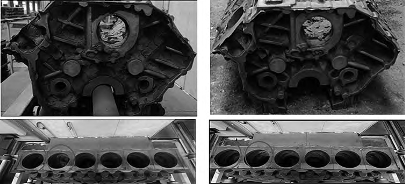
4.3 Case Study: 301B Body
The 301B body was originally bottom – cast. Although the liquid – metal flow and gas discharge were in the same direction and met the requirements of progressive solidification, the middle part of the finished product was thick, and there were problems with solidification and feeding, resulting in shrinkage cavities. The four wire – welding holes caused the liquid – metal flow to converge and entrain gas. Since adding gas plugs and increasing the casting temperature could not solve the shrinkage – cavity problem, the casting method was changed from bottom – casting to side – casting, and the four wire – welding holes were removed. After improvement, the liquid – metal flow was stable, the metal – filling time was short, and the thick part of the product was close to the riser, which was beneficial for feeding.
| Product Name | Initial Casting Method | Initial Defect | Improvement Measures | Improvement Effect |
|---|---|---|---|---|
| 301B Body | Bottom – casting | Shrinkage cavities in the thick middle part due to solidification and feeding problems | Change from bottom – casting to side – casting, remove four wire – welding holes | Stable liquid – metal flow, short metal – filling time, good feeding for the thick part of the product |
[Insert pictures here showing the casting process and defect comparison of 5561 (Balikun) and 301B Body before and after improvement]
5. Adjusting and Controlling the Casting Temperature
5.1 The Impact of Casting Temperature on Casting Quality
Aluminum is a metal that is easy to oxidize. The melting temperature needs to be controlled. If the melting temperature is too high, the aluminum liquid will be overheated, generating oxide skin and forming pores. If the melting temperature is too low, the aluminum liquid will cool unevenly, forming slag inclusions and pores. Therefore, it is necessary to control the melting temperature reasonably according to the material and thickness of the casting to avoid the generation of pores.
5.2 Appropriate Casting Temperature Ranges
The casting temperature ranges for different commonly used cast aluminum materials are shown in the following table:
| Material Code | Casting Temperature / ℃ (Average Wall Thickness < 5 mm) | Casting Temperature / ℃ (Average Wall Thickness ≥ 5 mm) |
|---|---|---|
| Pure Aluminum | 720 – 740 | 680 – 720 |
| ZL102 | 720 – 750 | 700 – 740 |
| ZL104 | 720 – 750 | 700 – 740 |
| ZL101A | 720 – 750 | 700 – 740 |
For example, for the 402 – clamp body with a wall thickness ≥ 5 mm, the casting – temperature range is 680 – 720 ℃. By performing flaw detection on the products cast at 680 ℃ and 710 ℃, it was found that the flaw – detection quality of the product was better at a higher temperature.
| Product Name | Wall – Thickness Condition | Casting Temperatures Tested | Flaw – Detection Results |
|---|---|---|---|
| 402 – clamp Body | Wall thickness ≥ 5 mm | 680 ℃, 710 ℃ | Better flaw – detection quality at 710 ℃ |
[Insert pictures here showing the 探伤 images of the 402 – clamp body at different casting temperatures]
6. Tilted Molds and Improved Casting Skills of Workers
6.1 The Role of Tilted Molds
Tilted molds are beneficial for the discharge of gas from the mold cavity. Generally, casting workers can place a piece of wood or iron bar at the back of the mold to tilt it. This simple operation can effectively improve the gas – discharge effect during the casting process.
6.2 The Importance of Controlling the Casting Speed
Controlling the casting speed is also crucial. If the casting speed is too fast, the aluminum liquid will tumble, which is not conducive to the smooth discharge of gas and will form pores. Therefore, it is necessary to control the casting speed reasonably according to the material and thickness of the casting to avoid the generation of pores.
[Insert a picture here showing the tilted – mold casting process]
7. Conclusion
To completely eliminate casting defects such as pores and shrinkage porosity in valve hall fittings, designers need to improve product design under the premise of meeting the connection and high – current – conduction requirements of the products. This can ensure that the product wall thickness changes evenly and the joints have smooth transitions. Process engineers should optimize the casting process, select different casting methods according to the characteristics of different products, and control the flow of molten metal. This can avoid the time – consuming and costly mold – improvement work. After the mold design is completed, measures such as adding gas plugs, cutting gas lines, changing the casting temperature, tilting the mold, and improving the casting skills of workers can be used to eliminate casting defects such as pores, shrinkage porosity, and shrinkage cavities during the production and casting process.
In general, by comprehensively considering and implementing these measures, the quality of valve hall fittings can be effectively improved, ensuring the stable operation of HVDC transmission systems.