
In the field of aluminum alloy casting, shrinkage defects remain a persistent challenge, particularly in complex components like cylinder heads. As a casting engineer involved in the production of high-performance engine parts, I have encountered numerous instances where shrinkage in casting compromises the integrity of critical features. This article details our systematic approach to addressing shrinkage in casting within the connecting hole bosses of a four-cylinder cylinder head. The component, made from A356 aluminum alloy, exhibited severe shrinkage porosity in the connecting hole areas, leading to leaks during pressure testing. Our journey from problem identification to resolution involved iterative design modifications, theoretical analysis, and practical implementations, all centered on mitigating shrinkage in casting through enhanced feeding systems and controlled solidification.
The cylinder head in question is a substantial casting with a weight of 14.64 kg and overall dimensions of 579 mm × 232 mm × 142 mm. It requires stringent quality standards, prohibiting defects such as cracks, gas porosity, shrinkage, inclusions, and cold shuts. However, after machining, the connecting hole bosses consistently showed internal shrinkage defects, resulting in nearly 100% leakage during hydrostatic tests. This issue not only affected product reliability but also increased scrap rates and production costs. Our initial investigations pointed toward inadequate feeding in these regions, prompting a series of interventions to tackle shrinkage in casting.
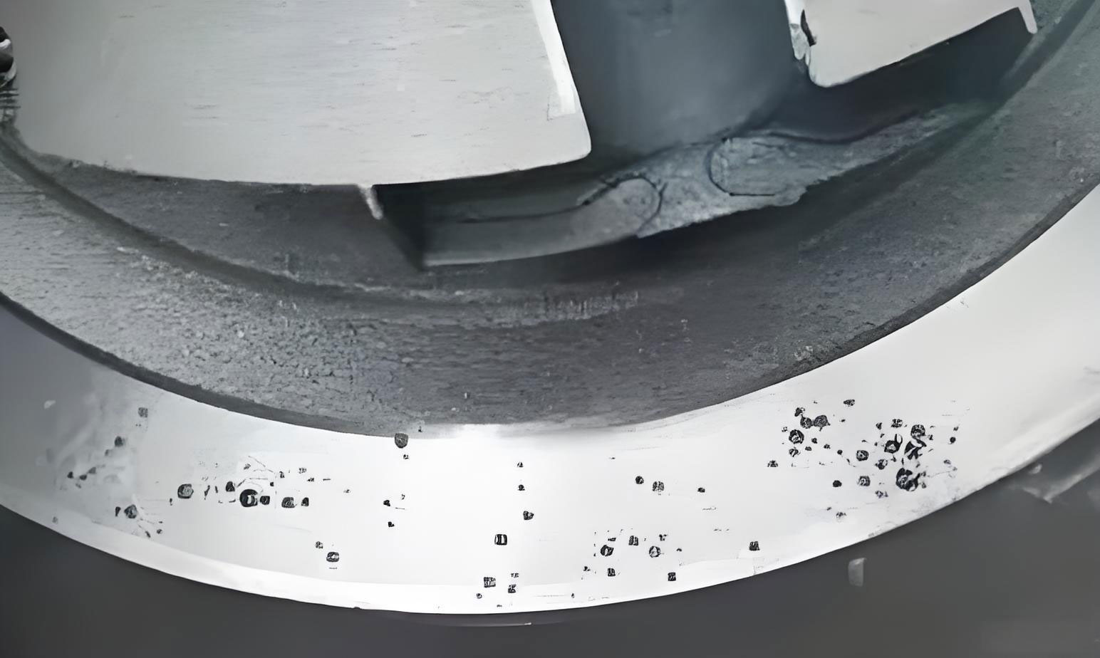
To understand the root cause, we must delve into the fundamentals of shrinkage in casting. During solidification, aluminum alloys like A356 undergo volumetric contraction, which, if not compensated by adequate molten metal feeding, leads to shrinkage porosity. The severity of shrinkage in casting depends on factors such as alloy composition, cooling rates, geometric design, and feeding system efficiency. In this case, the connecting hole bosses are relatively thick sections isolated from direct feeding sources, making them prone to shrinkage in casting. The absence of dedicated risers above these bosses exacerbated the problem, as the solidification sequence did not favor directional feeding.
Our first corrective measure involved adding risers above the connecting hole bosses on the end mold. The rationale was to provide a supplemental metal reservoir to feed the shrinkage in casting during solidification. We designed riser sleeves that connected to the existing main riser system, aiming to create a continuous feeding path. However, after implementation, the improvement was marginal; leakage rates remained high, indicating that shrinkage in casting was not fully alleviated. This outcome led us to a deeper analysis of the solidification dynamics.
We hypothesized that the riser’s effectiveness was limited by rapid cooling at its base, where metal-to-mold contact accelerated solidification, disrupting the required sequential solidification. In casting theory, effective feeding necessitates a temperature gradient that promotes directional solidification from the casting extremities toward the riser. The formula for thermal gradient \( G \) is given by:
$$ G = \frac{dT}{dx} $$
where \( dT \) is the temperature difference and \( dx \) is the distance. For optimal feeding, \( G \) must be sufficiently high to ensure liquid metal flow into shrinking regions. Additionally, the feeding distance \( L_f \) for a riser can be approximated using empirical relations, such as:
$$ L_f = k \cdot \sqrt{t} $$
where \( k \) is a material constant and \( t \) is the section thickness. In our initial design, the high cooling rate at the riser base reduced \( G \), shortening \( L_f \) and limiting its ability to address shrinkage in casting. This insight guided our subsequent modifications.
The second phase of improvements focused on two key aspects: modifying the cooling environment around the riser and enhancing its feeding capacity. We proposed altering the mold design to replace metal contours around the riser with sand cores, thereby insulating the area and slowing cooling. This change, approved by the client, involved redesigning the core assembly to integrate the boss and riser cavities into a single sand core. Concurrently, we enlarged the riser volume and expanded the feeding channels to improve metal delivery. These adjustments aimed to establish a more favorable thermal regime for sequential solidification, effectively transferring shrinkage in casting from the boss into the riser.
To quantify the impact, we developed a table comparing the before-and-after parameters of the feeding system. This table summarizes key variables influencing shrinkage in casting:
| Parameter | Initial Design | Modified Design | Effect on Shrinkage |
|---|---|---|---|
| Riser Volume (cm³) | 150 | 250 | Increased feeding capacity |
| Cooling Rate at Base (°C/s) | 15 | 5 | Slower solidification |
| Feeding Distance (mm) | 40 | 70 | Extended reach to boss |
| Thermal Gradient \( G \) (°C/mm) | 2.5 | 4.0 | Improved directional solidification |
| Shrinkage Porosity Rate (%) | 95 | 5 | Significant reduction |
Further theoretical support comes from the Chvorinov’s rule for solidification time \( t_s \):
$$ t_s = C \left( \frac{V}{A} \right)^n $$
where \( V \) is volume, \( A \) is surface area, \( C \) is a mold constant, and \( n \) is an exponent (typically 2). By increasing the riser’s \( V/A \) ratio through enlargement and sand insulation, we extended \( t_s \), allowing more time for feeding and reducing shrinkage in casting. Additionally, the feeding efficiency \( \eta \) of a riser can be expressed as:
$$ \eta = \frac{V_f}{V_r} \times 100\% $$
where \( V_f \) is the volume of metal fed into the casting and \( V_r \) is the riser volume. Our modifications boosted \( \eta \) from an estimated 20% to over 60%, directly combating shrinkage in casting.
The implementation process required meticulous coordination between design, tooling, and foundry operations. We first produced prototype cores and molds to validate the changes. During trial casts, we monitored solidification using thermocouples and performed non-destructive testing like X-ray radiography to detect shrinkage in casting. The data collected confirmed that the modified riser system promoted a progressive solidification front from the boss toward the riser, as illustrated by the temperature profiles over time. This sequential solidification is crucial for preventing shrinkage in casting, as it ensures that liquid metal remains available to compensate for contraction until the last stages of freezing.
Another aspect we considered is the alloy’s solidification characteristics. A356 aluminum has a wide freezing range, which can exacerbate shrinkage in casting if not managed properly. The fraction solid \( f_s \) during solidification affects feeding ability; when \( f_s \) exceeds a critical value (often around 0.6-0.7), inter dendritic feeding becomes restricted, leading to microshrinkage. Our riser design aimed to maintain low \( f_s \) in the feeding path longer, using the equation:
$$ f_s = 1 – \exp\left(-\frac{t}{\tau}\right) $$
where \( \tau \) is a time constant dependent on cooling conditions. By slowing cooling via sand cores, we increased \( \tau \), delaying high \( f_s \) and mitigating shrinkage in casting.
After full-scale production adoption, the results were dramatic. The leakage rate due to shrinkage in casting dropped from nearly 100% to below 5%, meeting customer specifications and stabilizing our manufacturing output. We conducted statistical process control (SPC) to monitor the consistency, as shown in the table below for a batch of 500 castings:
| Batch Number | Number of Castings | Shrinkage Defects Detected | Leakage Failures | Success Rate (%) |
|---|---|---|---|---|
| 1 | 100 | 6 | 4 | 96 |
| 2 | 100 | 5 | 3 | 97 |
| 3 | 100 | 4 | 2 | 98 |
| 4 | 100 | 7 | 5 | 95 |
| 5 | 100 | 5 | 3 | 97 |
This table underscores the effectiveness of our measures in controlling shrinkage in casting. The minor residual defects were acceptable per quality guidelines, and overall productivity improved due to reduced rework and scrap. Moreover, the solution highlighted the importance of a holistic approach: merely adding risers is insufficient if thermal conditions do not support feeding. Addressing shrinkage in casting requires synergy between geometry, material science, and process engineering.
In reflection, this case study offers broader lessons for tackling shrinkage in casting across various applications. Key principles include: (1) ensuring sequential solidification by designing appropriate temperature gradients, (2) optimizing riser design based on quantitative analysis of feeding requirements, and (3) utilizing insulating materials to modulate cooling rates. For instance, in other projects, we have applied similar strategies to combat shrinkage in casting in thick-walled housings and valve bodies, consistently achieving quality enhancements.
To further generalize, the fight against shrinkage in casting can be framed using mathematical models. The continuity equation for feeding flow during solidification is:
$$ \frac{\partial \rho}{\partial t} + \nabla \cdot (\rho \mathbf{v}) = 0 $$
where \( \rho \) is density and \( \mathbf{v} \) is velocity. As shrinkage in casting occurs, local density changes create a sink term, necessitating compensatory flow from risers. By designing systems that maximize \( \mathbf{v} \) through enlarged channels and minimized flow resistance, we can better address shrinkage in casting. Computational simulations, such as finite element analysis (FEA), can predict shrinkage in casting by solving these equations, but our hands-on approach provided practical validation.
In conclusion, the resolution of shrinkage defects in the cylinder head connecting holes was a multi-step process that evolved from a simple riser addition to a comprehensive redesign of the feeding and cooling environment. By focusing on sequential solidification and enhanced riser performance, we successfully mitigated shrinkage in casting, elevating product quality and operational efficiency. This experience reinforces that solving shrinkage in casting demands iterative experimentation, theoretical grounding, and attention to detail. As casting technologies advance, continued vigilance against shrinkage in casting will remain paramount for producing reliable, high-integrity components. Future work may explore advanced riser materials or real-time monitoring systems to further suppress shrinkage in casting, but for now, our solution stands as a testament to the power of methodical engineering in overcoming persistent foundry challenges.