
The production of motorcycle wheels via gravity casting in permanent molds represents a dominant manufacturing route, prized for its balance of cost-effectiveness and capability to produce components with adequate mechanical integrity. However, the evolving consumer market, which increasingly favors high-end, large-displacement motorcycles with premium aesthetic finishes, has placed unprecedented demands on surface quality. Traditional finishing processes like powder coating or painting can mask certain subsurface casting imperfections. This is not the case for plating—a chrome or similar electroplated finish—which acts as a mirror, revealing even the most subtle subsurface defects. The challenge of producing plating-grade aluminum alloy wheels, therefore, shifts the focus from mere functional integrity to achieving near-perfect internal soundness in the casting, particularly in critical cosmetic zones.
This work chronicles a first-hand investigation and resolution of shrinkage-related defects that manifested severely after polishing and plating operations. The subject was a new wheel design intended for a high-end application. Initial production trials revealed extensive micro-porosity and shrinkage cavities on the outer rim surfaces and central hub areas, rendering the parts entirely unsuitable for plating. The following narrative details the systematic approach undertaken, which integrated computational analysis, metallurgical principles, and empirical process refinement to eliminate these defects and achieve a consistent plating-quality surface.
Problem Manifestation: The Incompatibility of Shrinkage with Plating
The initial casting process, based on a conventional gravity die-casting mold design, produced wheels that passed standard quality checks for painted applications. However, upon aggressive polishing required as a pre-plate preparation, a network of fine, irregular pits and cavities became vividly apparent on the upper outer rim and spoke junctions. These were not surface blisters but sub-surface imperfections exposed by material removal.
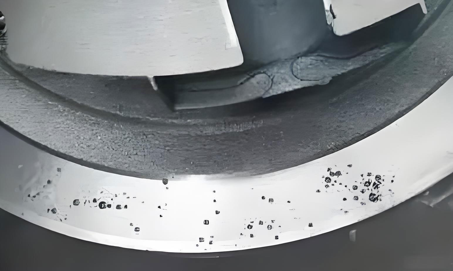
The defects exhibited classic characteristics of shrinkage in casting. On the rim, they appeared as irregular, rough-walled cavities—macro-shrinkage. On the spokes and hub, they manifested as diffuse, finely dispersed clusters of micro-porosity, often following a dendritic pattern visible under magnification. The electroplating process subsequently failed to bridge these pores; instead, it accentuated them, creating a visibly pitted and unacceptable final surface. This unequivocally identified the root cause as inadequate feeding and solidification control leading to volumetric shrinkage defects, not gas-related porosity.
Theoretical Foundation: Mechanisms of Shrinkage Formation in Castings
Understanding the defect required revisiting the fundamental physics of solidification. Aluminum alloys, including the common A356 type used for wheels, undergo significant volumetric contraction upon transitioning from liquid to solid state. This contraction, if not continuously compensated by feed metal from a reservoir (a riser or feeder), results in void formation. The morphology of the void—a concentrated pipe or a dispersed sponge—depends on the solidification mode.
The total volumetric contraction, $\Delta V_{total}$, can be expressed as the sum of contributions from liquid contraction, liquid-to-solid phase change, and solid-state contraction:
$$\Delta V_{total} = V_0 (\alpha_l \Delta T_l + \beta + \alpha_s \Delta T_s)$$
where $V_0$ is the initial volume, $\alpha_l$ and $\alpha_s$ are the coefficients of thermal contraction for the liquid and solid phases, $\Delta T_l$ and $\Delta T_s$ are the respective temperature drops, and $\beta$ is the volumetric solidification shrinkage factor (approximately 0.06-0.07 for aluminum-silicon alloys).
Shrinkage in casting occurs primarily during the phase change period. For alloys with a wide freezing range (mushy zone), like A356, solidification proceeds by the growth of a dendritic network. Isolated liquid pools become trapped between dendrite arms. When these final pools solidify and contract, feed metal cannot traverse the tortuous, blocked interdendritic pathways. This leads to the formation of numerous microscopic voids, known as micro-shrinkage or shrinkage porosity. The condition for its formation is succinctly captured by the Niyama criterion, a derivative of the thermal field during solidification. It posits that shrinkage porosity is likely when the local thermal gradient $G$ divided by the square root of the cooling rate $\dot{T}$ falls below a critical threshold $C_{Niyama}$:
$$ \frac{G}{\sqrt{\dot{T}}} < C_{Niyama} $$
A low $G/\sqrt{\dot{T}}$ value indicates a region that is cooling quickly but with a shallow temperature gradient—a condition typical of isolated hot spots that solidify late and are poorly fed.
Therefore, the strategy to eliminate shrinkage in casting revolves around ensuring directional solidification: creating a thermal gradient that progresses systematically from the extremities of the casting toward the feeders (risers). This ensures that a continuous liquid channel remains open to feed the volumetric shrinkage occurring in the solidifying regions.
Diagnostic Analysis: Integrating CAE Simulation and Physical Investigation
The investigation began with a comprehensive diagnosis using Computer-Aided Engineering (CAE) solidification simulation and physical dissection of defective castings.
| Defect Location | Defect Type | CAE Simulation Prediction | Physical Investigation (Dye Penetrant & Sectioning) | Probable Root Cause |
|---|---|---|---|---|
| Outer Rim (Upper Section) | Macro-shrinkage cavities & micro-porosity | High shrinkage tendency predicted in upper rim. | Dense shrinkage network increasing from bottom to top of rim. | Poor directional solidification; excessive riser spacing; insufficient riser efficiency. |
| Spoke Junctions (with rim or hub) | Dendritic micro-porosity clusters | Minor hot spots indicated. | Significant sub-surface porosity at thermal centers. | Localized hot spots with inadequate cooling and feeding. |
| Central Hub (around sprue) | Shrinkage porosity in core | Last-to-freeze zone identified in hub core. | Internal porosity in hub center. | Poor feeding path from sprue; excessive thermal mass. |
The simulation provided a crucial thermal map, revealing that the thermal gradients were not optimally oriented toward the risers. Physical sectioning of the rim quantified the problem: the wall thickness profile was nearly uniform (e.g., 18mm at bottom, 23-25.5mm at top), failing to establish a progressive increase in thermal mass needed for directional solidification. Furthermore, the distance between adjacent risers on the rim exceeded the effective feeding range for the alloy, creating an unfed “shadow zone.” In the hub, the geometry of the down-sprue (or biscuit) acted as a thermal mass without providing an effective feeding channel to the hub’s center, which solidified last and in isolation.
| Parameter | Value / Setting |
|---|---|
| Alloy | A356 (AlSi7Mg) |
| Pouring Temperature | 710 – 720 °C |
| Initial Mold Temperature (Upper/Lower) | ~450 °C / ~400 °C |
| Solidification Criteria | Niyama Criterion (G/√Ṫ) |
| Critical Shrinkage Threshold | Custom calibrated for A356 in wheel geometry |
Comprehensive Solution Strategy: A Multi-Pronged Attack on Shrinkage
The resolution required a holistic modification strategy targeting mold design, thermal management, and process parameters. Each defect zone demanded a specific set of actions, all governed by the principle of enhancing directional solidification and feeding efficiency.
1. Remediation for Rim Area Shrinkage
The rim was the most critical cosmetic area. The goal was to force solidification to start at the rim’s bottom (furthest from risers) and progress upwards towards the risers.
- Wall Thickness Gradient Optimization: The rim cross-section was redesigned to introduce a pronounced taper. The bottom was thinned, and the top (near the risers) was made thicker. This created a natural thermal gradient, making the top the thermal center that solidified last, perfectly aligned with the riser location.
- Riser (Feeder) System Enhancement: The distance between risers was reduced from 41mm to 25mm, bringing them within the effective feeding distance. Insulating blankets were added to the top of the mold blocks surrounding the risers. This dramatically slowed the cooling of the riser necks, keeping them liquid longer to feed the casting effectively. The feeding efficiency can be conceptually related to the modulus (Volume/Surface Area); the insulating pad increases the effective modulus of the riser neck.
- Aggressive Cooling at Rim Bottom: Cooling channel diameters in the lower mold section adjacent to the rim bottom were significantly increased. This intensified heat extraction at the initiation point of solidification, steepening the thermal gradient $G$ upwards. The enhanced cooling rate $\dot{T}$ at the bottom, combined with a higher $G$, directly improved the Niyama criterion value in that region, suppressing shrinkage in casting initiation.
2. Remediation for Spoke Junction and Hub Shrinkage
These are inherent hot spots due to intersecting geometry.
- Targeted Cooling at Hot Spots: Cooling channel diameters in the lower mold under spoke junctions were maximized (e.g., from Ø8mm to Ø20mm). For the central hub, the cooling around the down-sprue was intensified. This strategy aimed to reduce the local solidification time and shift the thermal center towards the feeding source.
- Feeding Path Optimization: The geometry of the down-sprue (biscuit) was modified. Instead of a blunt, chunky shape, it was redesigned to maintain a more open thermal connection (a larger “feeding channel”) to the hub core for a longer duration. This redesign was guided by ensuring the modulus of the feeding path was greater than that of the hub hot spot, as per Chvorinov’s rule for feeding.
3. Process Parameter Synchronization
Optimal mold design must be coupled with precise thermal control during the process cycle.
- Mold Temperature Control: Through iterative trials, an optimal mold operating temperature window was established. Crucially, it was found that the upper mold temperature, particularly in the riser/rim region, had to be maintained at a higher level than previously used for non-plated wheels.
| Mold Section | Initial Temperature Range (°C) | Optimized Temperature Range (°C) | Rationale |
|---|---|---|---|
| Upper Mold (Rim/Riser area) | 420 – 469 | 470 – 495 | Prevents premature freezing of riser neck; ensures adequate feed metal fluidity. |
| Lower Mold (Rim bottom, Spoke roots) | 380 – 420 | 410 – 430 | Provides sufficient heat to avoid mistuns but allows for gradient creation. |
| Lower Mold (Hub/Core area) | 390 – 420 | 350 – 370 | Aggressive cooling to shift thermal center and reduce hub solidification time. |
Production data correlated defect severity with upper mold temperature: severe shrinkage occurred below 450°C; micro-porosity persisted between 451-469°C; and sound castings were consistently produced within the 470-495°C window. This highlights that even with an improved design, the thermal dynamics during pouring are critical to mitigating shrinkage porosity.
4. Machining Allowance as a Final Safeguard
An unexpected finding during validation was the appearance of very superficial sub-surface pinholing in the hub area at the higher mold temperatures. This was attributed to slight gas entrapment or micro-shrinkage formation immediately beneath the skin in the very last-to-solidify areas, which became more susceptible at higher thermal levels. Rather than compromising the thermal strategy essential for internal soundness, the machining allowance on these specific hub faces was strategically increased from 1.5mm to 4.0mm. This guaranteed that this thin defective skin layer was completely removed during CNC machining, revealing the sound metal underneath without affecting the dimensional specification of the final part.
| Action Category | Specific Change | Target Defect | Intended Effect on Solidification |
|---|---|---|---|
| Mold Design | Tapered rim wall thickness | Rim shrinkage | Establishes directional solidification (thin-to-thick). |
| Reduced riser spacing + Insulating pads | Enhances feeding range and efficiency. | ||
| Optimized down-sprue geometry | Hub core shrinkage | Creates open feeding path to last-to-freeze zone. | |
| Thermal Management | Enlarged cooling channels (rim bottom, spokes, hub) | Rim, Spoke, Hub shrinkage | Increases thermal gradient G; reduces local solidification time. |
| Precise mold temperature control (see Table 3) | All shrinkage defects | Synchronizes mold thermal state with designed solidification sequence. | |
| Post-Casting | Increased machining allowance on hub | Sub-surface pinholes | Removes superficial defect layer without altering core process. |
Production Validation and Results
Implementing the full suite of modifications resulted in a dramatic improvement. CAE simulation of the revised design showed the shrinkage-prone areas successfully shifted entirely into the riser bodies, which are removed during processing. Physical validation on the foundry floor confirmed this.
Dye penetrant inspection of the as-cast outer rim showed a complete absence of the previously observed shrinkage network. After machining and polishing, the rim surfaces were perfectly smooth. Most significantly, after the electroplating process, the wheels exhibited a flawless, mirror-like finish with no evidence of pitting or porosity. The defect rate for plating-quality surfaces dropped from near 100% failure to a consistent process capability yielding over 95% acceptable parts. The success validated the multi-factorial approach: no single change was sufficient, but the synergistic effect of geometric redesign, enhanced cooling, intelligent heating (via temperature control and insulation), and strategic machining solved the complex problem of shrinkage in casting for a high-visibility application.
Conclusion
This investigation underscores that producing defect-free castings for severe cosmetic applications like plating requires a fundamental focus on controlling solidification to prevent shrinkage porosity. The key conclusions are:
- Shrinkage in casting is primarily a feeding problem solved by enforcing directional solidification. This is achieved through deliberate geometric design (wall thickness gradients), optimized riser placement and efficiency, and controlled thermal gradients via cooling and heating.
- Computational simulation (CAE) is an indispensable tool for diagnosing thermal issues and proactively validating mold design changes before costly tooling modifications.
- Mold temperature is not just a process variable but a critical design parameter. An optimal window exists where thermal gradients are maximized for feeding without creating other defects; for plating-grade wheels, this often necessitates running the mold, particularly feeder areas, at a higher temperature.
- A holistic view of the entire manufacturing process is essential. In this case, a collaborative adjustment between casting design (to manage bulk shrinkage) and machining planning (to remove superficial skin defects) provided the most robust and economical solution.
The methodologies developed—integrating simulation, targeted mold design, precise thermal control, and cross-process collaboration—provide a reliable framework for tackling similar challenges. They enable the production of high-integrity aluminum castings that meet the escalating aesthetic demands of premium markets, moving beyond mere functionality to achieve perfection in both form and finish.