
In our extensive experience at this manganese steel casting foundry, we have developed and refined a comprehensive set of technical conditions for producing high-manganese steel castings designed to withstand impact and abrasive wear in equipment such as crushers, grinders, and excavators. Through repeated practical application and summarization in production, we have established the following standards, which we now share for reference. These specifications are the cornerstone of quality assurance in our manganese steel casting foundry operations, ensuring that every component meets rigorous performance demands in harsh industrial environments.
The scope of this document covers ordinary high-manganese steel castings used under impact loading for wear resistance. All provisions are based on practical insights gained from our foundry’s production lines. The successful implementation of these standards relies on meticulous control at every stage, from melting and pouring to heat treatment and inspection, a philosophy deeply embedded in our manganese steel casting foundry culture.
Chemical Composition Requirements
The chemical composition of the castings must conform to the specifications outlined below. We differentiate between standard acceptance criteria and more stringent internal control limits used within our manganese steel casting foundry to ensure consistency and superior quality. The primary elements are carbon (C), manganese (Mn), silicon (Si), phosphorus (P), and sulfur (S).
| Element | Range | Notes |
|---|---|---|
| C | 1.00 – 1.35 | Type A: For simple-structure castings where wear resistance is primary (e.g., liner plates, jaw plates, mantles, concaves, rolls, shovel teeth). Type B: For complex-structure castings requiring high toughness (e.g., bucket front walls, track shoes, beams, grate plates). |
| Mn | 11.00 – 14.00 | |
| Si | 0.30 – 0.80 | Applicable to both types unless otherwise specified on drawings or through agreement with the customer. |
| P | ≤ 0.080 | |
| S | ≤ 0.050 |
For internal process control in our manganese steel casting foundry, we adhere to stricter limits to minimize variability and enhance product reliability. These internal controls are critical for maintaining the reputation of our manganese steel casting foundry as a leader in durable component manufacturing.
| Element | Control Range |
|---|---|
| C | 1.10 – 1.30 |
| Mn | 11.50 – 13.50 |
| Si | 0.40 – 0.70 |
| P | ≤ 0.060 |
| S | ≤ 0.040 |
The relationship between carbon content and toughness can be expressed by an empirical formula we use for preliminary assessment in our manganese steel casting foundry:
$$ T \approx k_1 – k_2 \cdot [C] $$
where \( T \) represents impact toughness (in J/cm²), \( [C] \) is the carbon content in weight percent, and \( k_1 \), \( k_2 \) are material constants specific to our melt practice. This guides our selection for Type A vs. Type B applications.
Geometric Dimension Tolerances
Castings must conform to the dimensions specified on the drawings. For dimensions without explicitly stated tolerances, the following tables apply. These tolerance standards are rigorously enforced in our manganese steel casting foundry to ensure proper fit and function in assembly.
| Nominal Size (mm) | Tolerance for Assembly Dimensions (mm) | Tolerance for Non-Assembly Dimensions (mm) |
|---|---|---|
| ≤ 500 | ± 2.0 | ± 3.0 |
| 500 – 1000 | ± 3.0 | ± 4.0 |
| 1000 – 1500 | ± 4.0 | ± 5.0 |
| 1500 – 2000 | ± 5.0 | ± 6.0 |
| 2000 – 2500 | ± 6.0 | ± 7.0 |
| > 2500 | ± 7.0 | ± 8.0 |
For cast holes, including semi-circular, square, or similarly shaped apertures, the tolerances are defined separately. This precision is vital for components produced in our manganese steel casting foundry, such as liner plates with mounting holes.
| Hole Diameter or Side Length (mm) | Tolerance for Assembly Holes (mm) | Tolerance for Non-Assembly Holes (mm) |
|---|---|---|
| ≤ 50 | +2.0, -1.0 | ± 2.0 |
| 50 – 100 | +2.5, -1.0 | ± 2.5 |
| > 100 | +3.0, -1.0 | ± 3.0 |
Flatness or straightness is controlled through deflection tolerance, measured on the assembly side of the casting. The allowable deflection \( \delta \) is given by:
$$ \delta \leq L / 1000 $$
where \( L \) is the length in mm, with maximum values capped as per Table 5. This ensures components from our manganese steel casting foundry mate correctly without excessive force.
| Length L (mm) | Maximum Allowable Deflection (mm) |
|---|---|
| ≤ 1000 | 2.0 |
| 1000 – 2000 | 3.0 |
| > 2000 | 4.0 |
For distances between holes, which are critical for bolted assemblies, tolerances follow a progressive scale. Our manganese steel casting foundry uses these to guarantee interchangeability.
| Nominal Distance (mm) | Allowable Tolerance (mm) |
|---|---|
| ≤ 250 | ± 1.0 |
| 250 – 500 | ± 1.5 |
| 500 – 1000 | ± 2.0 |
| > 1000 | ± 3.0 |
Surface Quality Specifications
All castings must be thoroughly cleaned of gates, risers, flash, fins, sand, and sand layers in internal cavities. For extremely difficult-to-clean internal cavities, residual core wires and sand may be allowed if they do not affect serviceability. Surface defects must not exceed the limits in Table 7. Any crack discovered must be ground or chipped out completely; cracks in critical areas exceeding 100 mm in length warrant rejection.
| Defect Type | Location | Maximum Allowable Size/Area | Notes |
|---|---|---|---|
| Gas Holes, Sand Inclusions, Slag Inclusions, Sand Adhesion, Scabs | Working Surfaces | Area per defect ≤ 400 mm², Depth ≤ 3 mm | For castings with wall thickness < 30 mm, defect depth must not exceed 1/4 of the wall thickness. The total area of defects on a given surface shall not exceed 5% of that surface area. |
| Assembly Surfaces | Area per defect ≤ 600 mm², Depth ≤ 4 mm | ||
| Non-working/Non-assembly Surfaces | Area per defect ≤ 800 mm², Depth ≤ 5 mm | ||
| Shrinkage Cavity in Riser Zone | Any surface | Area ≤ 1000 mm², Depth ≤ 8 mm | Measured after riser removal. |
| Local Depression/Protrusion | Any surface | Length ≤ 150 mm, Depth/Height ≤ 3 mm | Refers to unevenness not associated with other defect types. |
Defects exceeding Table 7 limits but within twice those values may be repaired. For individual castings where defects surpass these guidelines but do not severely impact quality, repair may be permitted after joint review and agreement. This balanced approach ensures efficiency in our manganese steel casting foundry without compromising integrity.
Heat Treatment and Microstructural Requirements
All castings must undergo water toughening (quenching) treatment. For castings over 1000 kg, test bars from the same melt must be heat-treated alongside and evaluated. The mechanical properties must meet:
- Tensile Strength: \( \sigma_b \geq 650 \, \text{MPa} \) (approximately \( 65 \, \text{kgf/mm}^2 \)).
- Impact Toughness: \( a_k \geq 150 \, \text{J/cm}^2 \) (approximately \( 15 \, \text{kgf·m/cm}^2 \)).
The test bar sampling follows a specific protocol: a separate Y-block or similar is poured during the middle of the casting process, with the sample taken from the central region as shown in the schematic (sample blank dimensions: approximately 30 mm x 30 mm x 150 mm).
Microstructural evaluation is paramount in our manganese steel casting foundry for quality control. The key aspects are:
- Carbide Rating: Carbides should not exceed Level 4 on the Carbide Rating Chart (First Rating Chart). If carbides exceed Level 2, re-heat treatment is required. The carbide morphology is classified from Level 1 (fully austenitic) to Level 12 (heavy network with undissolved and precipitated carbides). We define the carbide index \( C_I \) for internal tracking:
$$ C_I = f(N_c, S_c) $$
where \( N_c \) is the number of carbide particles per unit area and \( S_c \) is the average size. Levels 1-4 are acceptable for most applications from our manganese steel casting foundry. - Non-Metallic Inclusions: The total inclusion content (oxides + sulfides) must not exceed Level 3 on the Inclusion Rating Chart (Second Rating Chart). If inclusions are substandard but mechanical properties are合格, the casting is accepted; if mechanical properties also fail, it is scrapped. The inclusion volume fraction \( V_i \) is estimated as:
$$ V_i \approx \frac{\sum A_i}{A_{total}} \times 100\% $$
where \( A_i \) is the area of inclusions in a micrograph field. Levels 0-3 correspond to \( V_i < 0.1\% \). - Grain Size: The grain size of the test bar should be no coarser than ASTM No. 4. If overheating during melting causes coarse grains, the actual casting is examined: the sum of the columnar crystal lengths on both sides of a section must not exceed 50% of the section thickness. For castings with wall thickness ≤ 30 mm, columnar crystals are not permitted. Overheating in the test bar is allowed if isolated; severe overheating (all grains coarser than ASTM No. 0) requires tensile testing—if strength meets要求, it is accepted as second quality.
- Burning: Over-burning is not permitted. If detected in a test bar, the corresponding casting is inspected; if over-burned, it is scrapped.
After water toughening, castings may be straightened cold to correct distortion, provided the final deflection meets Table 5 limits. The straightening stress \( \sigma_s \) must satisfy:
$$ \sigma_s \leq 0.7 \, \sigma_{y} $$
where \( \sigma_{y} \) is the yield strength of the toughened material, to avoid inducing cracks.
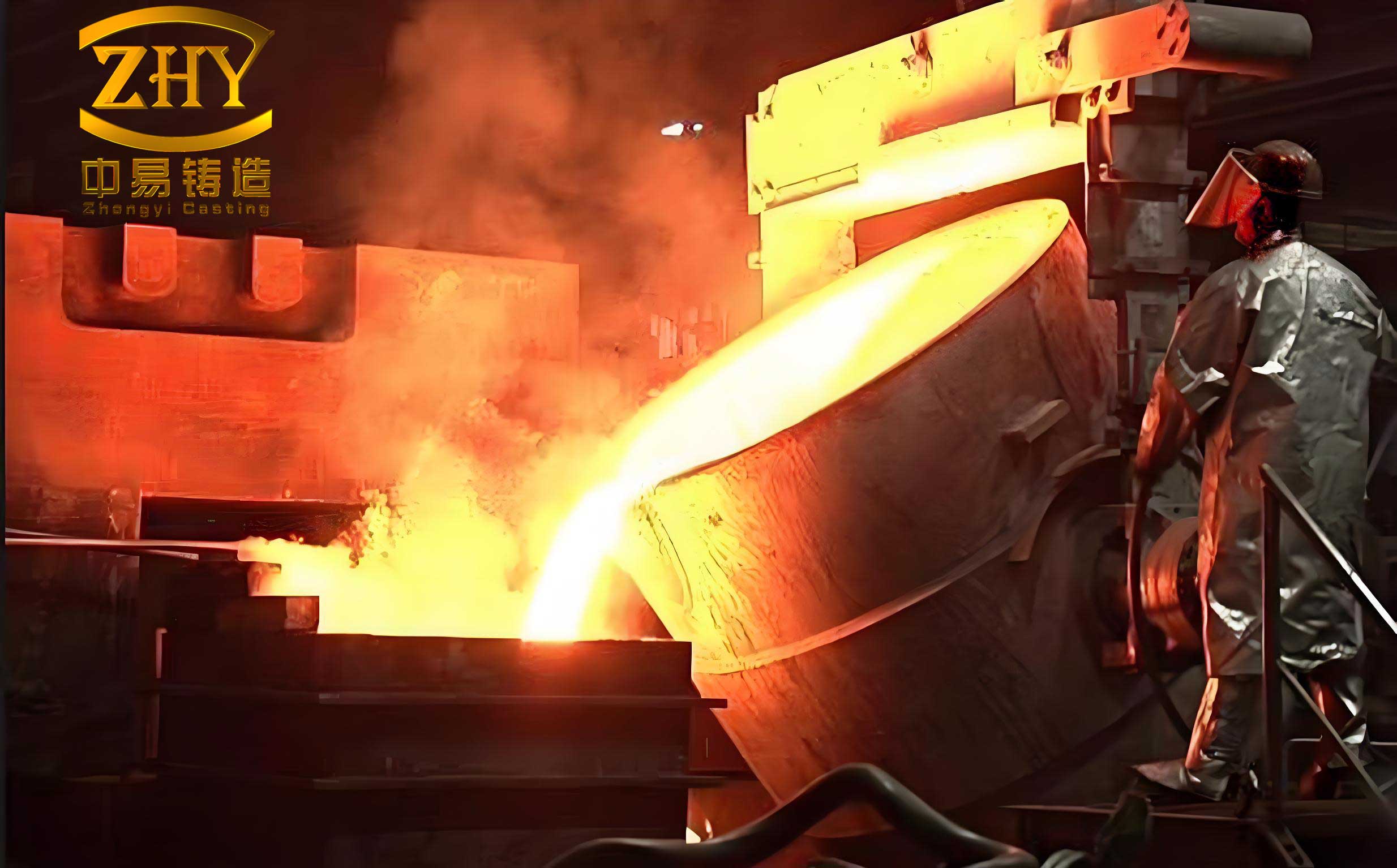
The image above illustrates a typical high-manganese steel casting produced in our facility, showcasing the complex geometry and robust construction achievable through adherence to these specifications. It serves as a visual testament to the capabilities of our manganese steel casting foundry.
Inspection Rules and Test Methods
Our Quality Inspection Department conducts acceptance based on: Chemical Composition, Geometric Dimensions & Surface Quality, Total Inclusions, Grain Size, and Carbide/Burning status. The workflow is integral to the operation of our manganese steel casting foundry.
- Chemical Analysis: Performed for every melt by sampling from the ladle during tapping or mid-pour. Analysis accuracy must meet relevant national standards.
- Mechanical Testing: Tensile and impact tests are performed weekly on sampled test bars. Impact testing follows standard Charpy V-notch procedures; tensile testing follows standard uniaxial methods. The impact energy \( A_k \) is calculated as:
$$ A_k = \frac{E_f}{A} $$
where \( E_f \) is the fracture energy and \( A \) is the cross-sectional area at the notch. - Metallographic Examination: Grain size, inclusions, carbides, and burning are checked for every melt and heat treatment batch. Grain size is rated per ASTM E112. For product复查, samples are taken from mid-thickness locations and from the midpoint between feeder and end of solidification.
Marking and Certification
Each casting shipped from our manganese steel casting foundry is accompanied by a product quality certificate signed by the technical inspector. For castings over 50 kg, the foundry mark, year-month of production, and part number are cast onto the component. This traceability is essential for quality assurance and customer confidence in our manganese steel casting foundry products.
Detailed Microstructural Rating Descriptions
To provide clarity without referencing specific image numbers, here is a verbal description of the carbide and inclusion rating systems employed in our manganese steel casting foundry. These descriptions are based on microscopic examination at 500x magnification with a field of view less than 2 mm in diameter.
Carbide Rating (First Rating Chart):
- Level 1: Fully austenitic matrix with no visible carbides.
- Level 2: Fine short linear or dotted carbides partially distributed along grain boundaries.
- Level 3: Carbides as short fine lines and dots forming a broken network at grain boundaries.
- Level 4: Grain boundary carbides similar to Level 3, with isolated undissolved granular or small blocky carbides within grains or boundaries.
- Level 5: Carbides precipitated as fine stringers and small颗粒, distributed along部分 grain boundaries.
- Level 6: Carbides as short lines, dots, and some short stringers/small颗粒 forming a network at boundaries.
- Level 7: Similar boundary network as Level 6, with no more than 3 undissolved small blocky carbides.
- Level 8: Carbides precipitated as fine stringers forming a broken boundary network.
- Level 9: Boundary carbides as Level 8, with a few undissolved large granular or small blocky carbides.
- Level 10: Carbides as fine stringers forming a continuous boundary network.
- Level 11: Fine linear or stringer carbides at boundaries, some with feathery morphology;少量 acicular carbides within grains.
- Level 12: Numerous undissolved medium/small blocks and granular carbides.
- Level 13: Heavy precipitation of fine stringer carbides at boundaries and numerous acicular carbides within.
- Level 14: Abundant undissolved small blocks, stringers, and granular carbides.
- Level 15: Heavy precipitation of carbides, fine stringers, and sorbitic structures.
Note: Levels 1-4 are typically acceptable. Levels 11-15 represent unacceptable structures often due to high carbon or improper heat treatment. In our manganese steel casting foundry, we aim for Levels 1-3 for optimal toughness.
Inclusion Rating (Second Rating Chart for Total Inclusions):
- Level 0: Essentially free of visible inclusions.
- Level 1: Sparse, small inclusions with diameter约 0.1 mm.
- Level 2: Moderate number of inclusions, some up to 0.2 mm.
- Level 3: More frequent inclusions, some clustering, up to 0.3 mm.
- Level 4: Heavy inclusion content, large aggregates, detrimental to properties.
Inclusions are not separated into oxides and sulfheres for this总 rating; the notation “TOx+S” denotes the total. Our manganese steel casting foundry controls to Level 2 or better to ensure performance.
Technical Discussions and Foundry Practices
In the daily operations of our manganese steel casting foundry, several key points warrant deeper discussion. The water toughening process involves heating castings to approximately 1050-1100°C, holding for sufficient time to dissolve carbides, then rapidly quenching in water. The quenching rate \( \dot{T} \) must exceed a critical value to avoid carbide reprecipitation:
$$ \dot{T} > \frac{dC}{dt} \cdot \frac{\partial T}{\partial C} $$
where \( C \) is carbon concentration in austenite. We monitor this closely to achieve full austenitization.
The presence of columnar crystals is assessed because they can reduce transverse properties. For a section of thickness \( t \), the acceptability criterion is:
$$ L_{col,left} + L_{col,right} \leq 0.5 \times t $$
This is checked for castings from melts suspected of过热.
Regarding inclusions, our experience in the manganese steel casting foundry shows that controlling total inclusions to Level 3 or better generally does not adversely affect service life, even in demanding applications like shovel teeth. However, higher levels necessitate mechanical property verification.
Overheating and over-burning are distinguished: overheating may cause grain growth but can be remedied if properties are adequate; over-burning involves incipient melting and is irreparable. Our strict no-over-burning policy underscores the commitment to quality in this manganese steel casting foundry.
The empirical relationship between hardness and wear resistance in our manganese steel casting foundry products is often approximated by:
$$ W_R \propto H^{n} $$
where \( H \) is hardness (in HB) and \( n \) is an exponent around 2 for abrasion. However, the high work-hardening capacity of manganese steel means initial hardness is less critical than in-service hardening.
Finally, the economic aspect of rework versus scrap is managed through the defect tolerance tables. Our manganese steel casting foundry aims to minimize waste while ensuring every component meets the stringent requirements for impact-abrasion service.
In conclusion, the technical conditions detailed herein represent the collective wisdom and rigorous standards developed through years of dedicated practice in our manganese steel casting foundry. They encompass chemical, dimensional, surface, mechanical, and microstructural controls, all aimed at producing reliable, long-lasting high-manganese steel castings for the most demanding industrial applications. Continuous improvement remains our goal, and we share these specifications to foster knowledge exchange within the broader foundry community. Adherence to these principles ensures that every casting leaving our manganese steel casting foundry embodies the durability and performance our customers depend on.