
In my extensive experience as a thermal engineering specialist involved in industrial furnace upgrades, I have overseen numerous projects aimed at enhancing process efficiency and product quality. One particularly impactful endeavor was the comprehensive technological transformation of a casting welding heat treatment furnace at a large-scale agricultural machinery manufacturing facility. The primary driver for this retrofit was the urgent need to address persistent heat treatment defects in critical cast components, such as engine blocks, gearboxes, and rear axle housings. These heat treatment defects, including uneven heating, excessive thermal stresses, and insufficient tempering, directly led to high rejection rates during post-weld inspections. This article details my first-hand account of the furnace改造, leveraging extensive data, theoretical analyses, and practical implementations. I will emphasize how systematic modifications can drastically reduce heat treatment defects. The core objective was to create a furnace environment that ensures precise, uniform thermal profiles, thereby eliminating the root causes of common heat treatment defects.
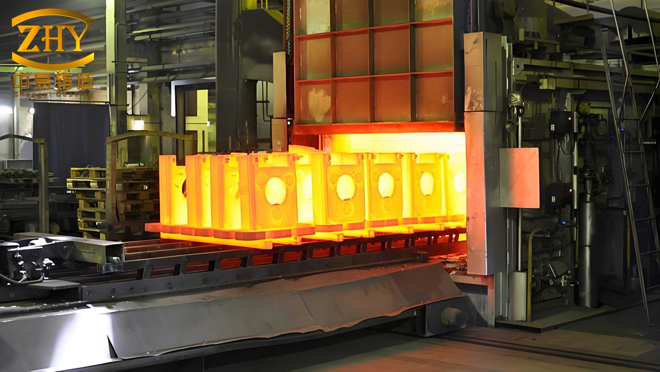
The original furnace was a double-layer, mechanical through-type unit approximately 12 meters in length, utilizing producer gas. Its primary function was the post-weld heat treatment of large castings, with single pieces weighing up to 1.2 tons. The specified heating curves, especially for complex geometries like cylinder blocks with wall thicknesses varying from 5 mm to 80 mm, were demanding. The process required heating from ambient to 650°C for welding and subsequent annealing at 550°C, with strict mandates on heating rates and soaking times to prevent heat treatment defects such as warpage, cracking, or residual stress concentrations. The original furnace’s performance was inadequate, leading to non-uniform temperature distribution—a direct precursor to heat treatment defects. Components would often exhibit “half-red, half-black” conditions, a clear indicator of severe thermal gradients causing inconsistent material properties and promoting heat treatment defects in the heat-affected zones of welds.
To systematically address the sources of heat treatment defects, we must first understand the fundamental thermal principles governing furnace operation. The uniformity of temperature (T_unif) within the workspace can be modeled as a function of heat input distribution, combustion efficiency, and thermal losses. A key metric is the temperature differential (ΔT), which directly correlates with the risk of heat treatment defects.
$$
\Delta T_{max} = T_{hotspot} – T_{coldspot} = f\left( \dot{Q}_{burner}, \eta_{comb}, k_{wall}, \dot{m}_{gas} \right)
$$
Where $\dot{Q}_{burner}$ is the heat release rate per burner, $\eta_{comb}$ is the combustion efficiency, $k_{wall}$ is the effective thermal conductivity of the furnace lining, and $\dot{m}_{gas}$ is the mass flow rate of fuel. Minimizing ΔT_max is paramount to avoiding heat treatment defects. The original furnace suffered from poor $\eta_{comb}$ and uneven $\dot{Q}_{burner}$ distribution.
The following table categorizes the major heat treatment defects observed prior to the retrofit, their probable causes linked to furnace performance, and the associated impact on product quality.
| Heat Treatment Defect Type | Primary Furnace-Related Cause | Resultant Quality Impact |
|---|---|---|
| Uneven Hardness/Softness | Non-uniform temperature distribution (High ΔT) | Localized stress points, reduced fatigue life |
| Warpage and Distortion | Rapid or asymmetric heating/cooling rates | Geometric inaccuracies, assembly failures |
| Quench Cracks (in related processes) | Excessive thermal gradients before welding/annealing | Catastrophic part failure |
| Incomplete Stress Relief | Insufficient soak time at target temperature due to slow heating | Dimensional instability during machining |
| Surface Oxidation/Scaling | Localized over-heating and improper atmosphere | Poor surface finish, requiring rework |
The original high-speed burners were a significant source of problems. Their complex design made maintenance arduous, and their narrow air passages were prone to clogging. This led to poor air-fuel mixing, incomplete combustion, and erratic flame patterns. The resulting inefficient and uneven heat release was a fundamental cause of the temperature disparities that induced heat treatment defects. Furthermore, the burner placement along the furnace did not support the required bottom-heating profile for large, massive castings. The furnace hearth structure was another critical flaw. The supporting brickwork for the load-bearing rails was unstable, leading to rail sagging or lifting. This not only caused mechanical damage to the furnace roof but also altered the distance between the workpiece and heat sources, creating unpredictable hot and cold zones that fostered heat treatment defects. Additionally, the original flue design located in the annealing zone sidewall wasted substantial thermal energy, reduced overall furnace efficiency, and caused unacceptably high workpiece temperatures at the discharge end, posing environmental hazards and potentially inducing heat treatment defects from uncontrolled cooling.
The改造 strategy was holistic, targeting each identified weakness to systematically eradicate the conditions that breed heat treatment defects. The first and most crucial step was the replacement of the high-speed burners with a custom-designed, sleeve-type burner. Our design prioritized robustness and simplicity to ensure stable operation even under fluctuating gas pressures. The burner’s ability to provide a stable, diffuse flame was critical for achieving a uniform radiative and convective heat transfer environment, essential for preventing localized heat treatment defects. During commissioning, we encountered combustion noise exceeding 90 dB. Analysis revealed it was due to an excessive pressure differential between the gas and air streams. The relationship for combustion noise (L) can be approximated by:
$$
L \propto 10 \log_{10}\left( \frac{\Delta P_{air-gas}}{\rho \cdot c^3} \cdot \dot{V}_{mix} \right)
$$
Where $\Delta P_{air-gas}$ is the pressure differential, $\rho$ is the density of the mixture, $c$ is the speed of sound, and $\dot{V}_{mix}$ is the volumetric flow rate of the air-fuel mixture. By carefully adjusting the regulator settings to minimize $\Delta P_{air-gas}$, we successfully reduced operational noise to below 80 dB, improving the working environment without compromising combustion stability that could lead to heat treatment defects.
The reconfiguration of the burner layout was geometrically optimized to support the required thermal profile. We transitioned to a dedicated lower heating zone strategy. New combustion chambers were constructed in the annealing zone sidewalls, interconnected yet independently controllable. This allowed for precise zoning and the creation of a tailored temperature gradient along the furnace length, which is vital for controlling heating rates and minimizing thermal shock—a key factor in preventing warpage-related heat treatment defects. The number and spacing were calculated based on heat flux requirements. The theoretical heat flux ($q”$) needed at the workpiece surface to achieve the desired heating rate ($\frac{dT}{dt}$) for a casting of density $\rho_c$, specific heat $C_p$, and thickness $L$ is:
$$
q” = \rho_c \cdot C_p \cdot L \cdot \frac{dT}{dt}
$$
The total burner capacity ($\sum \dot{Q}_{burner}$) was then sized to meet this demand across the entire hearth area, with a safety factor, ensuring no lag in heating that might cause heat treatment defects.
The furnace hearth was completely redesigned to achieve monolithic integrity. The refractory foundation, rail sleepers, and supporting structures were interlocked into a single, coherent assembly. This eliminated relative movement, ensured permanent rail alignment, and guaranteed a consistent and repeatable spatial relationship between the heat sources and every workpiece. Consistency in this geometry is a basic but often overlooked prerequisite for avoiding positional-dependent heat treatment defects. To harness waste heat and improve thermal efficiency, we integrated a combined air and gas recuperator into the furnace arch at the discharge end of the annealing zone. This unit serves a dual purpose: preheating combustion air and fuel gas, and acting as a heat sink to lower the temperature of outgoing workpieces. The effectiveness ($\epsilon$) of such a recuperator is defined as:
$$
\epsilon = \frac{T_{air,out} – T_{air,in}}{T_{flue,in} – T_{air,in}}
$$
where $T_{air,in/out}$ are the air inlet/outlet temperatures and $T_{flue,in}$ is the entering flue gas temperature. By increasing the initial temperature of the reactants, we raise the adiabatic flame temperature, enhancing heat transfer rates and allowing for lower fuel consumption to maintain the same furnace temperature. More importantly, a faster heat-up rate reduces the time components spend in intermediate temperature ranges where certain heat treatment defects like temper embrittlement can initiate. The table below summarizes the key design changes and their intended effect on mitigating heat treatment defects.
| Component Modified | Modification Description | Direct Impact on Heat Treatment Defect Risk |
|---|---|---|
| Burner System | Replaced high-speed burners with custom sleeve-type burners; optimized pressure balance. | Improved temperature uniformity; reduced localized overheating/cooling causing defects. |
| Burner Layout & Heating Zones | Implemented dedicated lower heating zones with independently controlled side-wall burners. | Enabled precise control of heating curve, minimizing thermal gradients and warpage. |
| Furnace Hearth Structure | Created monolithic refractory-rail structure for enhanced stability. | Eliminated variable workpiece positioning, ensuring consistent heat exposure. |
| Heat Recovery System | Installed integrated air/gas recuperator in the annealing zone arch. | Increased heating rates and thermal efficiency; lowered discharge temperature for controlled cooling. |
| Flue System | Eliminated side-wall flue in annealing zone; redirected flow through recuperator. | Improved heat distribution and utilization, reducing cold spots. |
The post-transformation performance data unequivocally demonstrates the success of our approach in combating heat treatment defects. The most significant metric was the dramatic drop in the scrap rate for critical engine cylinder blocks, from approximately 15% to below 5%. This improvement is directly attributable to the elimination of uneven heating, which was the progenitor of most observed heat treatment defects. The furnace now consistently produces the required thermal profile. The temperature uniformity, measured as ΔT across the workpiece load, improved from a range of ±50°C to within ±10°C. This level of control is fundamental to preventing the suite of heat treatment defects listed in Table 1. Operationally, the new burners offer excellent adjustability. Operators can now fine-tune zones in real-time to accommodate different parts and工艺, a flexibility that further guards against process-induced heat treatment defects. The environmental and energy metrics also showed remarkable gains. The integrated recuperator preheats combustion air to approximately 250°C and fuel gas to about 200°C. The overall furnace thermal efficiency (η) saw a substantial increase. We can calculate the efficiency improvement based on specific energy consumption (SEC):
$$
\eta \approx \frac{Q_{theoretical}}{Q_{input}} \propto \frac{1}{SEC}
$$
Where $Q_{theoretical}$ is the useful heat absorbed by the workpieces and $Q_{input}$ is the heat content of the fuel consumed. The specific energy consumption decreased from 1.8 Gcal/ton of treated castings to 1.1 Gcal/ton, representing an energy saving of nearly 39%. This reduction in fuel use also implies a more stable and cleaner combustion process, contributing to a more consistent furnace atmosphere and indirectly reducing surface-related heat treatment defects like excessive scaling. The following table provides a quantitative before-and-after comparison of key performance indicators, all of which relate to the propensity for heat treatment defects.
| Performance Indicator | Before Transformation | After Transformation | Improvement / Implication for Defects |
|---|---|---|---|
| Temperature Uniformity (ΔT across load) | ± 50 °C | ± 10 °C | Major reduction in thermal gradient-driven defects. |
| Cylinder Block Scrap Rate (due to HT defects) | ~15% | <5% | Direct evidence of significant quality improvement. |
| Specific Energy Consumption | 1.8 Gcal/ton | 1.1 Gcal/ton | Higher efficiency promotes stable, controlled heating. |
| Combustion Air Preheat Temperature | Ambient (~30°C) | 250 °C | Enables faster heating rates, reducing time for defect formation. |
| Workpiece Discharge Temperature | Excessively High (>300°C) | Controlled (~150°C) | Allows for planned cooling, preventing stress-related defects. |
| Burner Maintenance Downtime | High (Frequent clogging) | Low (Robust design) | Ensures process consistency, avoiding variability-induced defects. |
| Operational Noise Level | >90 dB | <80 dB | Improved environment, but no direct defect link. |
The theoretical underpinnings of the reduced heat treatment defects can be further explored through the lens of heat transfer and stress analysis. The rate of temperature change within a casting is governed by the Fourier heat equation. For a one-dimensional approximation through a critical section of thickness L, the temperature field T(x,t) is:
$$
\frac{\partial T}{\partial t} = \alpha \frac{\partial^2 T}{\partial x^2}
$$
where $\alpha$ is the thermal diffusivity. A non-uniform boundary heat flux, as present in the old furnace, leads to large spatial variations in $\frac{\partial^2 T}{\partial x^2}$, causing high thermal stresses ($\sigma_{thermal}$). These stresses, which can exceed the material’s yield strength at elevated temperatures, are a primary cause of plastic deformation and cracking—classic heat treatment defects. The induced thermal stress can be approximated by:
$$
\sigma_{thermal} \approx E \cdot \beta \cdot \Delta T_{local}
$$
where $E$ is Young’s modulus, $\beta$ is the coefficient of thermal expansion, and $\Delta T_{local}$ is the temperature difference across a micro-region of the part. By minimizing $\Delta T_{local}$ through superior furnace uniformity, we directly reduce $\sigma_{thermal}$, thereby mitigating the risk of distortion and crack-related heat treatment defects. The改造 directly addressed the boundary condition (heat flux q” at the surface) to make it as uniform as possible, leading to a more homogeneous solution to the heat equation.
In conclusion, from my direct involvement in this project, the technological transformation of the casting welding heat treatment furnace was a resounding success, fundamentally rooted in a deep understanding of the origins of heat treatment defects. The project transcended a simple equipment upgrade; it was a systematic re-engineering of the thermal processing environment. By replacing problematic burners, optimizing the heat application geometry, reinforcing the furnace structure, and implementing intelligent heat recovery, we created a system capable of delivering precise, repeatable, and uniform thermal cycles. This capability is the ultimate defense against heat treatment defects. The results—a drastic fall in scrap rates, significant energy savings, improved working conditions, and enhanced operational flexibility—validate the approach. The key lesson is that combating heat treatment defects requires a holistic view of the furnace as a system where combustion science, heat transfer mechanics, and structural integrity converge. Continuous monitoring and data analysis remain essential, as even the best-designed furnace must be meticulously operated and maintained to keep the ever-present risk of heat treatment defects at bay. This project stands as a testament to the fact that targeted engineering interventions, guided by fundamental principles and a focus on uniformity, can effectively eliminate the costly and quality-compromising spectrum of heat treatment defects in industrial foundry operations.