
Abstract:
This article introduces a comprehensive process scheme for manufacturing ductile iron planetary shelves utilizing the DISA vertical molding line. Through rigorous product structure analysis and computer-aided casting simulation, various aspects of the casting process were meticulously designed, including the selection of the parting surface, sand core design, pouring system, and riser configuration. Effective feeding measures were implemented for the hot spots. The large end face facilitated sequential solidification with the assistance of risers, while the small end face leveraged graphite expansion for self-feeding to mitigate shrinkage porosity defects. Trial production results validated the casting quality, aligning with standards in metallographic structure and mechanical properties, devoid of shrinkage porosity, thereby affirming the feasibility of the adopted process scheme.
1. Introduction
Planetary shelves play a pivotal role in planetary gear transmission devices, responsible for load bearing, power transmission, and load distribution. They are components subject to the highest external torque in the mechanism, necessitating lightweight design, rigidity, and freedom from shrinkage porosity defects. This paper presents a casting process design for a dual-sided integral planetary shelf produced on a DISA vertical molding line, focusing on ensuring casting quality and efficiency.
2. Product Structure and Hot Spot Analysis
The planetary shelf in question features a dual-sided integral structure, with maximum outer dimensions of ϕ245 mm × 98 mm, wall thicknesses ranging from 13 to 22 mm, and a raw mass of 9.8 kg. Made from QT500-7 material, its structure comprises two circular side plates and four evenly spaced support pillars, forming a spatial frame. The distance between the two side plates is approximately 60 mm, with intricate internal structures.
2.1 Analysis of Casting Hot Spots
When designing the casting process for ductile iron castings, the primary consideration is the issue of shrinkage porosity, necessitating close attention to hot spot locations. Casting hot spots are categorized into structural hot spots and process hot spots. Structural hot spots arise from the geometric shape of the casting, where metal accumulates the most and releases the greatest heat during solidification. Process hot spots result from casting process requirements, such as the placement of risers, ingates, and vent holes, potentially upgrading existing structural hot spots.
Due to their extended solidification time and significant volumetric shrinkage, hot spots are prone to shrinkage porosity defects in the absence of feeding measures. In our design, structural hot spots, mainly concentrated at the junctions between the side plates and support pillars, were targeted for feeding, while process hot spots were avoided.
3. Casting Simulation Analysis
To further analyze the hot spots and potential shrinkage porosity defects, AnyCasting software was employed for CAE analysis of the casting solidification sequence and defect probability. The initial casting temperature was set to 1,385 °C, with other parameters at software defaults.
From the simulation results, the small end side plates exhibited shorter solidification times due to their larger heat dissipation area, despite having geometrically similar hot spot sizes to the large end side plates. CAE analysis of shrinkage porosity defects indicated that over 30% of defects were evenly distributed across the eight structural hot spots. The small end face, with better heat dissipation and smaller hot spots, prioritized self-feeding or the use of chill plates to eliminate shrinkage porosity. Conversely, the larger hot spots on the large end face required designed risers for feeding.
4. Casting Process Design
4.1 Selection of Parting Surface Location
Considering the structural characteristics of the casting and the wet sand production conditions, the DISA vertical parting no-box squeeze molding line was chosen. Two options for parting surface selection. Scheme 1 offers simpler sand cores and uniform machining allowances but poses challenges for riser feeding to the hot spots on the large end flange, located approximately 45 mm away. Scheme 2 facilitates the placement of the pouring gate near the hot spots on the large end side plate, aiding in feeding. DISA molding line characteristics and better heat dissipation at the small end side plate hot spots favored Scheme 2, despite its more complex sand cores and uneven machining allowances.
4.2 Sand Core Design
Following DISA manual guidelines, the sand core design incorporated positive pressure plate core head positioning and clamping surfaces, with a -0.1 to -0.3 mm gap for automatic core setting in the mold cavity and 0 to 0.5 mm gaps elsewhere. The sand cores were prepared using a 20 L cold-box core machine.
4.3 Pouring System and Riser Design
The pouring system design focused on the ingate location, influencing mold temperature distribution, solidification and cooling patterns, and ultimately casting quality. The ingates were positioned between the two support pillars on the large end face to enable a single riser to feed two hot spots simultaneously.
With DISA mold plate dimensions of 600 mm × 480 mm, two castings were arranged per mold. Considering the longer solidification time of the large end face hot spots compared to the small end face, the large end face was oriented inward for riser feeding, while the small end face faced outward, in a relatively cooler zone away from the pouring gate, optimizing heat dissipation and solidification.
To achieve sequential solidification and feed two castings simultaneously, two ϕ70 mm cylindrical risers, connected by a 30 mm × 8 mm thin plate to prevent interference, were designed to feed the four hot spots on the large end face. The ingates were designed as 60 mm × 12 mm wide strips to align with the hot spots on both sides of the support pillars. Venting slots and ceramic foam filters were incorporated to reduce mold cavity pressure, optimize feeding, prevent internal sand adhesion, and purify the molten iron.
Table 1. Chemical Composition of Molten Iron (Mass Fraction, %)
| Element | C | Si | Mn | P | S | Mg | Sn |
|---|---|---|---|---|---|---|---|
| Content | 3.6~3.8 | 2.5~2.8 | 0.1~0.4 | <0.06 | <0.02 | 0.03~0.05 | 0.02~0.04 |
5. Casting CAE Simulation Results
Based on the preliminary process design, a 3D model was created and simulated using AnyCasting software. The simulation revealed that the small end face began solidifying first, with isolated liquid phases appearing mid-solidification. Graphite expansion self-feeding or chill plates could eliminate shrinkage porosity risks, with further adjustments if necessary. The large end face achieved sequential solidification with adequate riser feeding, presenting no shrinkage porosity risks.
6. Melting Process
Molten iron was prepared using a medium-frequency induction furnace, with nodulization and inoculation treatment via wire feeding units, supplemented by in-stream inoculation during pouring to enhance iron properties. The pouring temperature ranged from 1,370 to 1,390 °C.
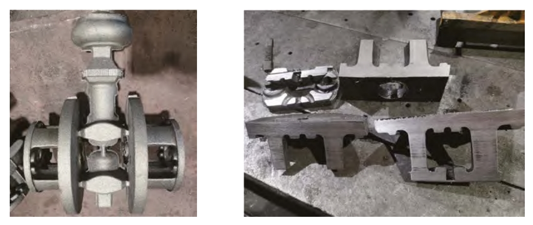
7. Trial Production Validation
Trial castings were produced according to the designed process. The metallographic structure of the trial castings, The final casting and pouring system. Anatomical inspection of the planetary shelf casting confirmed no shrinkage porosity. The castings met quality standards, with an 85% nodularity rate, maximum graphite sphere diameter of 6 μm, 45% pearlite content, tensile strength of 527 MPa, elongation of 11%, and hardness of 187 HBW.