
The Lost Foam Casting (EPC) process presents unique challenges for steel foundries, with slag inclusions and gas porosity being among the most prevalent and detrimental defects. These imperfections significantly impact the mechanical properties and surface quality of cast components, particularly for thicker sections and low-carbon steels. This analysis delves into the origins, formation mechanisms, and mitigation strategies for slag inclusions in EPC steel castings, drawing upon principles of fluid dynamics, thermodynamics, and kinetics.
The high incidence of defects such as slag inclusions, gas holes, and carbon pickup in EPC steel castings, often exceeding 60-80% in some production scenarios, underscores the complexity of the process. For thin-walled castings, defects tend to concentrate near gate and riser connections. In contrast, thicker sections frequently exhibit subsurface slag inclusions, typically located 1-3 mm beneath the casting skin within a band 10-30 mm deep. The morphology of these slag inclusions is irregular, appearing as clustered agglomerates with fuzzy boundaries and varying contrast in microstructural analysis, making them difficult to remove by machining.
| Casting Type | Primary Defects | Typical Location | Main Contributing Factors |
|---|---|---|---|
| Thin-wall, “Three-Resistance”* | Gas holes, slag holes, shrinkage | Junctions with gates/risers | Localized overheating, prolonged metal retention, gas/slag accumulation. |
| Thick-wall Sections | Subsurface slag inclusions | 1-3mm below surface, 10-30mm band | High initial slag content, filling dynamics, negative pressure effects, solidification sequence. |
| Low-Carbon Steel | Uneven surface carburization | Surface layer (1-3mm) | Decomposition of foam pattern (pyrolysis). |
| *”Three-Resistance”: Wear-resistant, Heat-resistant, Corrosion-resistant. | |||
Sources and Nature of Slag Inclusions
The formation of slag inclusions in EPC steel castings is fundamentally linked to the introduction and behavior of non-metallic phases within the molten steel. The primary sources can be categorized as follows:
- Pyrolysis Residues from the Foam Pattern: The vaporization and thermal degradation of the expanded polystyrene (EPS) or similar foam pattern is a unique source of slag. The complex hydrocarbons break down, producing gaseous products and a carbonaceous residue. This residue can become entrapped as slag inclusions. The amount and nature of this residue are influenced by pattern density and the specific polymer used.
- Inherent Melting Slag and Dissolved Gases: As in any steelmaking process, the melt derived from scrap steel and other charge materials contains inherent oxides, sulfides, and other impurities that form slag. Furthermore, molten steel can dissolve gases like hydrogen and nitrogen, which may precipitate during solidification, often nucleating on existing slag particles to form combined slag-gas holes.
- Reoxidation Products: Turbulent flow during mold filling can expose fresh steel to air or oxidizing atmospheres within the mold cavity, leading to the formation of fresh iron oxide and other oxidation slags.
- Coating Material Incursions: The refractory coating on the foam pattern can be a significant source of mechanical slag. If the coating penetrates into pattern glue joints or cut surface voids, it forms brittle “coating spikes” into the cavity. These spikes are easily eroded by the flowing metal, releasing particulate matter into the stream.
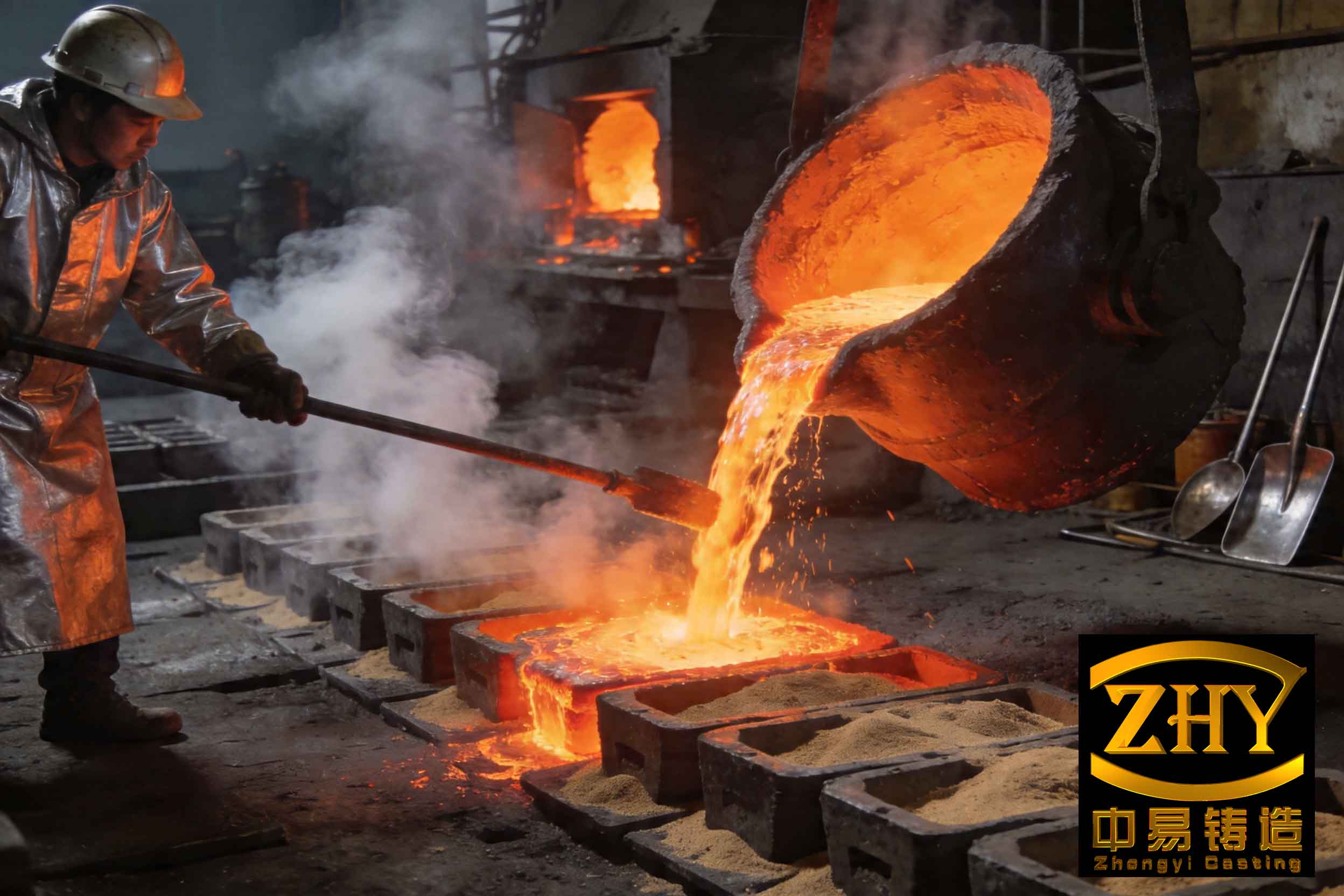
The Peculiarities of Filling in EPC and Their Impact on Slag Inclusion Formation
The EPC filling process is radically different from conventional cavity molding. The gradual displacement and decomposition of the foam pattern by the advancing metal front create a dynamic interface. Two critical phenomena exacerbated by the application of vacuum (negative pressure) are central to the entrapment of slag inclusions.
Turbulent Flow Regime
While some level of turbulence exists in all casting processes, the application of vacuum in EPC for ferrous alloys intensifies this to a detrimental degree. The rapid removal of gases through the coating and sand matrix creates pressure differentials that destabilize the liquid metal front. Instead of a smooth, advancing front, it becomes highly disturbed, with pronounced “fingering” and backward eddies. This severe turbulence promotes the engulfment of both gaseous and solid decomposition products from the foam, preventing their escape and dispersing them throughout the melt. The Reynolds number $(Re)$ characterizing this flow is high, indicating a dominant inertial over viscous forces:
$$Re = \frac{\rho v L}{\mu}$$
where $\rho$ is the density of steel, $v$ is the local flow velocity, $L$ is a characteristic length (e.g., hydraulic diameter of the flow path), and $\mu$ is the dynamic viscosity. High $Re$ flow directly increases the propensity for slag inclusion entrapment.
Wall Attachment Effect
Negative pressure applied from the sides and bottom of the flask creates a powerful “wall attachment” or “skin effect.” The molten metal is drawn preferentially towards the cooler mold walls coated with refractory, causing it to solidify rapidly upon contact. This forms a thin, solidified or highly viscous skin along the casting walls early in the filling process. Consequently, the metal advances in a U-shaped profile, with the central core of the cavity filling more slowly. This effect has several consequences for slag inclusions:
- It creates a physical barrier that hinders the lateral escape of slag particles and gases towards the mold walls and the vacuum ports.
- It alters the temperature gradient, potentially causing premature solidification in areas where slag might otherwise float out.
- It can trap the pyrolysis gases from the yet-to-decompose core of the foam pattern, increasing back-pressure and the likelihood of gas entrapment with slag.
The pressure difference driving this wall flow can be related to the applied vacuum $(P_{vac})$ and the pressure in the gas gap $(P_{gap})$ at the metal-foam interface:
$$\Delta P_{wall} \propto P_{gap} – P_{vac}$$
A higher $\Delta P_{wall}$ intensifies the wall attachment effect.
| Condition | Metal Front Profile | Flow Nature | Slag/Gas Entrapment Risk |
|---|---|---|---|
| Non-Ferrous, No Vacuum | Relatively smooth, forward-sweeping | Laminar to mildly turbulent | Moderate |
| Ferrous, With Vacuum (Standard) | Highly disturbed, U-shaped with wall skin | Highly turbulent | Very High |
| Ferrous, Minimized Vacuum | Moderately disturbed | Turbulent, but reduced | Moderate to High |
Thermodynamic and Kinetic Analysis of Slag Inclusion Formation and Movement
The formation and final location of slag inclusions are governed by the interplay of thermodynamic driving forces and kinetic constraints.
Thermodynamics of Formation
The formation of oxide-based slags from re-oxidation is thermodynamically favored at steel pouring temperatures. For example, the free energy change $(\Delta G)$ for the formation of iron oxide (wüstite, FeO) is negative:
$$2Fe_{(l)} + O_{2(g)} \rightarrow 2FeO_{(s/l)} \quad \Delta G < 0$$
Similarly, the decomposition of the hydrocarbon foam pattern is a complex pyrolysis reaction yielding solid carbon and various gases. The carbon can dissolve into the steel (causing carburization) or remain as solid particles that act as nuclei for other slags. The overall stability and composition of the resulting multiphase slag inclusions depend on local conditions of temperature, oxygen potential, and the presence of other elements like Si, Mn, and Al.
Kinetics of Flotation and Removal
The movement of slag particles in molten steel is primarily governed by Stokes’ law, which describes their buoyant rise velocity $(v_s)$ in a quiet melt:
$$v_s = \frac{2 g r^2 ( \rho_m – \rho_s )}{9 \eta}$$
where $g$ is gravity, $r$ is the radius of the (assumed spherical) slag particle, $\rho_m$ and $\rho_s$ are the densities of molten steel and slag respectively, and $\eta$ is the viscosity of molten steel.
This equation highlights the critical factors for slag removal:
- Particle Size ($r$): The rise velocity is proportional to $r^2$. Doubling the particle radius increases its rise rate by a factor of four. Small particles (e.g., finely dispersed pyrolysis carbon or reoxidation products) have negligible rise velocities and are easily trapped by the advancing solidification front, forming dispersed slag inclusions.
- Density Difference ($\rho_m – \rho_s$): Slags are less dense than steel, providing the buoyant force. However, complex, agglomerated slags may have varying effective densities.
- Melt Viscosity ($\eta$): Higher viscosity, often related to lower superheat, slows slag flotation.
In the dynamic, turbulent environment of EPC filling, the simple Stokes regime is rarely achieved. The kinetic path for slag removal is hindered by:
- Turbulent Dispersion: Eddy currents keep small particles in suspension and can even drive them downward or sideways.
- Opposing Flow Directions: The natural buoyant rise of slag (vertical) is orthogonal to the dominant vacuum-driven flow towards the mold walls (lateral/horizontal). This misalignment drastically reduces the efficiency of slag transport to potential escape paths.
- Early Solidification Skin: The wall attachment effect creates a solidified barrier before many slag particles have had time to float to the top of the melt pool, effectively trapping them in the subsurface zone.
The effective distance a slag particle can travel before being captured by the solidus is given by a kinetic relationship combining its rise velocity and the local solidification rate $R$:
$$d_{max} = v_s \times t_{liquid} = \frac{v_s \cdot \Delta T_{crit}}{R \cdot G}$$
where $t_{liquid}$ is the local liquid lifetime, $\Delta T_{crit}$ is the critical freezing range, and $G$ is the temperature gradient. A high $R$ or a low $v_s$ results in a small $d_{max}$, ensuring the particle will be entrapped as an inclusion.
Integrated Pathways and Recommendations for Reducing Slag Inclusions
Mitigating slag inclusions in EPC steel castings requires a multi-faceted approach targeting the sources, the filling behavior, and the removal mechanisms.
1. Minimizing Primary Slag Content
Melt Treatment: Employ ladle refining techniques, fluxing, or filtration to reduce the native slag content of the steel before pouring. Ceramic foam filters in the gating system can effectively trap larger inclusions. Using slag coagulants that agglomerate fine particles into larger ones capitalizes on the $r^2$ dependence in Stokes’ law, dramatically improving their floatation kinetics.
Pattern Material: Use low-density foam patterns to minimize the mass of pyrolysis residues. Ensure patterns are fully dried to avoid steam generation.
2. Optimizing Process Parameters to Favor Slag Exclusion
Gating System Design: Aim for simplicity. Avoid one-box-multiple castings layouts that require long, complex runner systems prone to turbulence, cooling, and reoxidation. Direct, short gating that promotes the most tranquil fill possible is ideal.
Pattern Assembly Quality: Minimize glue joints and ensure they are smooth, without excess glue (adds residue) or gaps (allow coating penetration). When cutting foam, be aware that cut surfaces open cell structures, creating pits that can hold coating; sealing these surfaces can be beneficial.
Vacuum Strategy – The Critical Control:
| Parameter | Standard Practice (Problematic) | Recommended Practice | Rationale |
|---|---|---|---|
| Vacuum Level | High (e.g., >0.05 MPa) | Minimal necessary to prevent mold collapse (e.g., 0.03-0.04 MPa for steel) | Reduces turbulence and the intensity of the wall attachment effect. |
| Vacuum Direction | Side/Bottom extraction only | Top extraction (top-covered flask) where feasible | Aligns vacuum-induced flow with natural buoyant slag rise, creating a synergistic slag-removal effect. |
| Application Timing | Constant high vacuum during pour | Possible stepped vacuum: lower during fill, higher during solidification for rigidity | Allows for calmer filling while maintaining mold strength during the critical solidification phase. |
The benefits of reduced vacuum and top extraction can be conceptualized by modifying the driving force equation for slag transport. The net velocity of a slag particle $(v_{net})$ becomes a vector sum of its Stokes rise velocity and any vacuum-induced velocity $(v_{vac})$:
$$\vec{v_{net}} = \vec{v_s} + \vec{v_{vac}}$$
With side/bottom vacuum, $\vec{v_{vac}}$ is largely horizontal, doing little to aid the vertical $\vec{v_s}$. With top vacuum, $\vec{v_{vac}}$ is vertical and upward, directly augmenting $\vec{v_s}$, thereby maximizing $v_{net}$ and the efficiency of slag removal from the melt.
3. Coating and Sand Properties
A coating with high high-temperature permeability allows pyrolysis gases to escape quickly and uniformly, minimizing the gas gap pressure $(P_{gap})$ and reducing turbulent fluctuations at the metal front. A stable, erosion-resistant coating minimizes mechanical breakdown and the introduction of coating material as a source of slag inclusions.
In conclusion, the prevalence of slag inclusions in EPC steel castings is not an intractable aspect of the process but a consequence of specific physical and chemical interactions. The key lies in understanding that the standard application of high side-vacuum, while solving the mold rigidity problem, simultaneously creates the hydrodynamic conditions most favorable for defect generation. A paradigm shift towards minimizing vacuum during filling, optimizing its direction, and rigorously controlling upstream sources of slag offers a clear pathway to significantly higher quality EPC steel castings. The fight against slag inclusions is won by carefully balancing the thermodynamics of slag formation with the kinetics of its removal, all while managing the unique fluid dynamics of the disappearing foam cavity.