
Abstract: In the production of grinding machines, disc-cover, flat-plate, square, and short cylindrical hydraulic components are commonly seen. Although these components have simple shapes and structures, they feature large cross-sectional thicknesses, high technical requirements, and high reject rates in casting (ranging from 30% to 40%). By applying a centrifugal slag-collecting ladle, adopting the “horizontal casting and vertical pouring” process, utilizing continuous casting of multiple pieces from one billet, and introducing the concept of modulus, this paper presents effective measures to address these challenges, ensuring the yield and quality of castings for hydraulic components in grinding machines.
Keywords: grinding machine; hydraulic components; centrifugal slag collecting ladle; horizontal vertical casting; continuous casting; modulus
1. Introduction
The main products of Zhengzhou Second Machine Tool Plant are various types and specifications of internal grinding machines. Many actions of the internal grinding machine during operation, such as the reciprocating motion of the worktable, the lateral feed motion of the grinding wheel (rapid feed, working feed, rapid retreat), the automatic clamping of the workpiece, and the tilting and lifting actions of the dresser, are all achieved hydraulically, naturally requiring the use of numerous hydraulic components (hereinafter collectively referred to as machine tool hydraulic components). Among them, disc-cover, flat-plate, square, and short cylindrical components are the most common. Although these components have simple external structures, they have thick cross-sections and mainly require control over internal quality, demanding high strength, high density, and certain hardness.
2. Disc-Cover Hydraulic Components
This type of casting includes end covers for various hydraulic cylinders, end covers and cover plates for various valve bodies, etc. These castings generally have smaller dimensions but greater thicknesses. When designing the process, considerations must be given to feeding issues. At the same time, to improve the process yield rate, the scheme of multiple castings from one mold using a shared gating system is often selected.
Due to the small size of these parts, the molten metal cools quickly after pouring, and the slag that enters the mold cavity floats to the top and encounters greater resistance, often becoming trapped in the casting, resulting in “slag eyes” and causing scrap. The most effective way to avoid slag defects in such castings is to prevent slag from entering the mold cavity. On the one hand, slag blocking should be done well during pouring; on the other hand, the slag removal performance of the gating system should be enhanced.
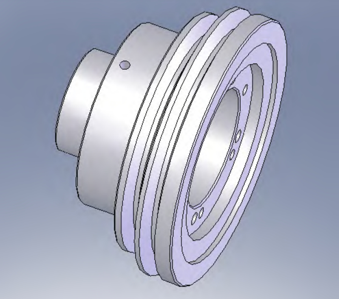
2.1 Case Study: Receiver Casting
The receiver is one of the key components of the feed hydraulic cylinder for the M224 semi-automatic internal grinding machine. The original process used green sand mold wet casting with the technical key points being “using pouring as feeding” and two castings per mold sharing a common straight runner (also serving as a riser). The castings produced by this process were often scrapped due to slag defects, with a scrap rate of 35%.
The improved casting process for the receiver. The revised process involves two castings sharing a pouring system, with the original straight runner replaced by a centrifugal slag-collecting ladle. The parameters of the slag-collecting ladle are designed based on the hot-spot diameter of the casting, serving dual functions of slag removal and feeding.
| Casting Component | Weight (kg) | Outline Dimension (mm) | Material | Maximum Thickness (mm) | Scrap Rate |
|---|---|---|---|---|---|
| Receiver | 7.9 | φ180 × 45 | HT200 | 42 | 35% (original); <4% (improved) |
2.2 Case Study: Clamping Hydraulic Cylinder Casting
The clamping cylinder casting for the M224 internal grinding machine is a composite casting with both a pulley and a hydraulic cylinder function. The original process had high scrap rates due to turbulent metal flow in the straight runner, which easily entrained slag into the mold cavity, causing “slag eyes” in the castings, and metal splashes forming “iron beans.”
The casting is located in the lower mold, with two castings per mold. A slag-collecting ladle (also serving as an insurance riser) is placed in the middle between the two castings.
| Casting Component | Weight (kg) | Outline Dimension (mm) | Material | Maximum Hot-Spot Diameter (mm) | Scrap Rate |
|---|---|---|---|---|---|
| Clamping Hydraulic Cylinder | 11.5 | φ186 × 120 | HT200 | 50 | ~30% (original); 3% (improved) |
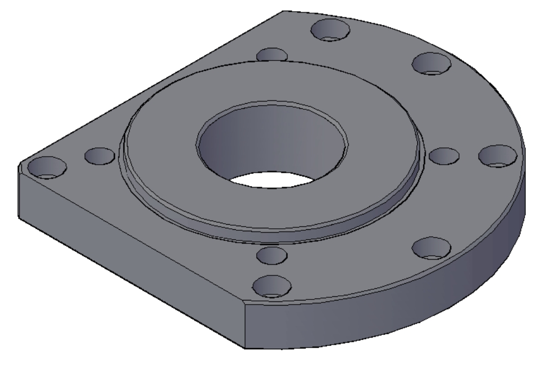
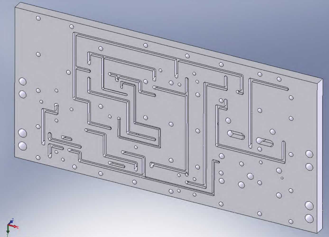
3. Plate-Type Hydraulic Components
This type of casting includes distribution plates, cover plates, etc., for the oil supply and distribution system of various internal grinding machines. All surfaces of these parts are machined, with the two large planes being the most critical areas. These planes often require the machining of many oil grooves, oil holes, and mounting holes, demanding dense structure and freedom from any casting defects such as porosity, slag eyes, etc.
The “horizontal casting and vertical pouring” dry mold process is adopted, with the two large planes positioned on the side in the pouring position, ensuring better quality.
3.1 Case Study: Distribution Plate Casting
The distribution plate for the M224 semi-automatic internal grinding machine is a critical component of the oil supply and distribution system. The casting process for the distribution plate.
| Casting Component | Weight (kg) | Outline Dimension (mm) | Material | Machining Allowance (mm) | Scrap Rate |
|---|---|---|---|---|---|
| Distribution Plate | 48 | 596 × 312 × 34 | HT200 | Side, bottom: 6; Top: 10 | <3% |
4. Square and Short Cylindrical Hydraulic Components
Components such as various control valve bodies on grinding machines, such as reciprocating control boxes, feed control boxes, double-pressure relief valves, stroke valves, and on/off valves, are mostly square or short cylindrical in shape.
When cast one piece per billet, defects such as porosity and slag holes often occur on the upper surface of the pouring position, with a scrap rate of around 35%, and sometimes even up to 40%.
Adopting the process of continuous casting of multiple pieces from one billet and “horizontal casting and vertical pouring” has yielded significant results.
4.1 Case Study: Reciprocating Control Box Casting
The casting process for the reciprocating control box. Four castings are cast from one billet.
| Casting Component | Material | Outline Dimension (mm) | Weight (kg) | Defect Requirements | Scrap Rate | Process Yield Rate |
|---|---|---|---|---|---|---|
| Reciprocating Control Box | HT300 | 148 × 150 × 108 | 19 | No slag eyes, sand holes, porosity, etc. | <4% | 80.5% |
5. Material Performance Assurance
One characteristic of hydraulic component production is the high material performance requirements for castings, such as strength, hardness, and structural density. To meet these requirements, the following aspects should be considered:
- Chemical Composition Control: Select appropriate chemical compositions based on the performance requirements and wall thickness of the castings, correctly calculate the charging ratio, and strictly control the quality of raw materials (stable composition).
- Cooling Rate Control: Strictly control the key factors and links that affect the cooling rate of castings during production. For instance, the concept of modulus can be introduced to facilitate the organization of production and ensure the material performance requirements of castings.
5.1 Modulus Concept Introduction
The modulus is an important parameter for controlling the cooling rate of castings. Table 1 lists the modulus calculation formulas for several common geometric shapes.
| Serial Number | Geometric Shape | Modulus (M) Calculation Formula |
|---|---|---|
| 1 | Flat Plate or Circular Plate (a ≥ 5T) | M = T / 2 |
| 2 | Rectangular Bar | M = ab / [2(a + b)] |
| 3 | Solid Cylinder (h ≤ 2.5D) | M = rh / [2(r + h)]<br>Long Cylinder (h > 2.5D): M = D / 4 |
| 4 | Hollow Cylinder (b < 5a) | M = ab / [2(a + b)]<br>Hollow Tube (b > 5a): M = a / 2 |
6. Conclusion
For disc and cover-type hydraulic components, a pouring system with a centrifugal slag-collecting bag is selected, which serves the dual purposes of slag removal and shrinkage compensation, resulting in high process yield and finished product rates. The “horizontal molding and vertical pouring” process is adopted for flat-plate hydraulic components, meeting the high-quality requirements of the two major planes with satisfactory results. For block and short cylindrical hydraulic components, the “multi-piece continuous casting in one mold” and “horizontal molding and vertical pouring” processes are employed to ensure controlled quality. The concept of modulus is introduced in the casting of hydraulic components. By calculating and comparing the moduli of various geometric bodies, it provides a basis for accurately controlling the cooling rate of castings and ensuring their performance requirements.