
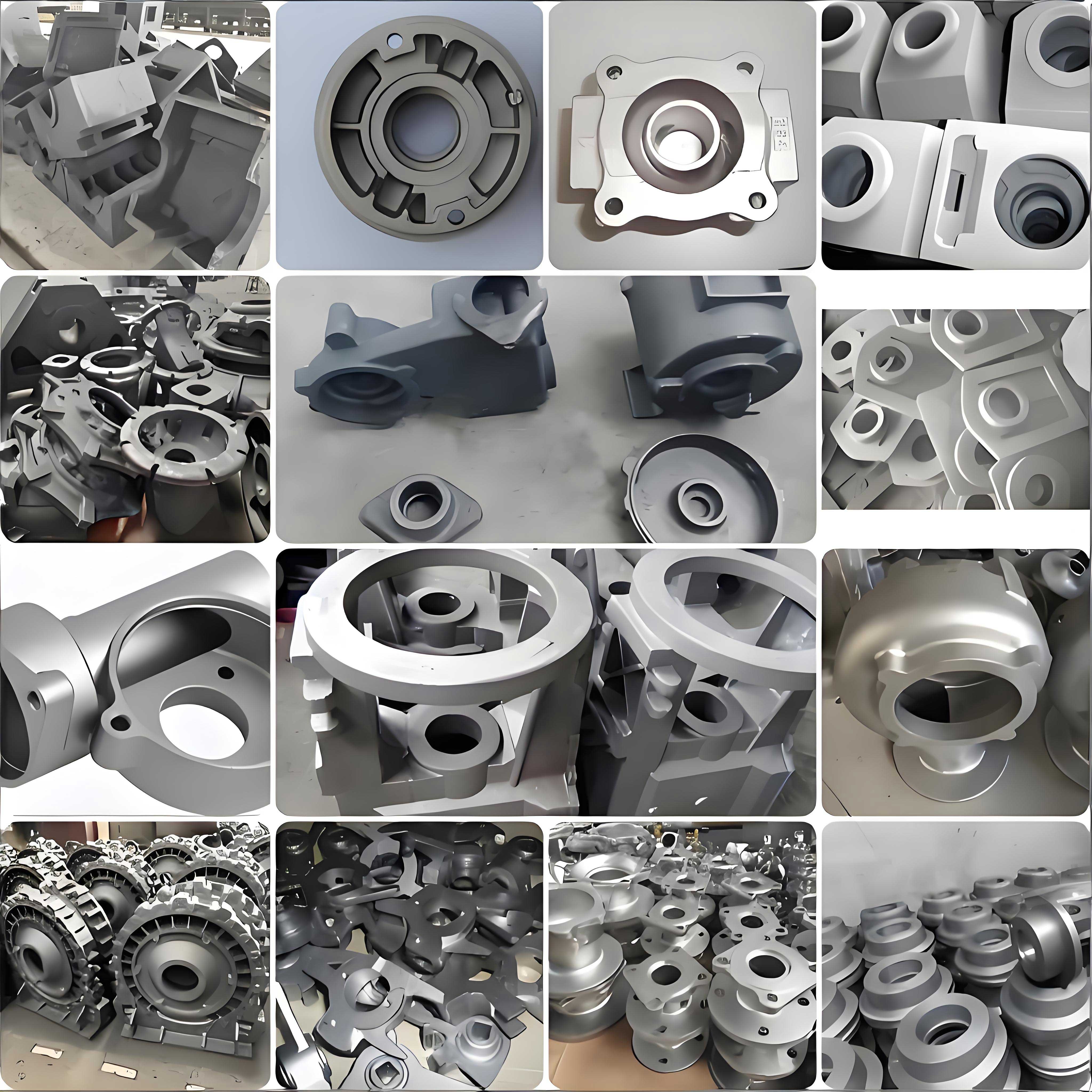
In my extensive work with ferrous alloys, the unique position of nodular cast iron has always been a focal point of both industrial necessity and metallurgical intrigue. The fundamental characteristic that sets this material apart is the presence of carbon in the form of spherical graphite nodules embedded within the metallic matrix. This spheroidal morphology drastically reduces the notch effect typically associated with flake graphite in gray irons, granting nodular cast iron a superior combination of ductility and tensile strength that often rivals that of steel under certain conditions. Its remarkable versatility has led to widespread adoption across critical sectors such as automotive components (crankshafts, differential carriers, brake calipers), pipe systems, heavy-duty gears, axles, agricultural machinery, and railway applications. The ability of austempered nodular cast iron to offer high strength with reduced weight further solidifies its role as a replacement for forged and welded steel components in demanding applications. However, this very utility brings forth a significant technical challenge: welding and repair. The production of nodular cast iron components is not without its difficulties, and a relatively high scrap rate is often reported, partly due to the complexities involved in achieving sound, reliable welded repairs. This necessity drives my deep interest in understanding and optimizing the welding processes for nodular cast iron.
From a metallurgical standpoint, the welding of nodular cast iron is essentially an exercise in localized casting and rapid solidification. The process involves a compact, transient冶金 sequence of melting and subsequent solidification of a small weld pool. The thermal cycle is intense; heat input is localized, and the subsequent cooling rates are extraordinarily high due to the significant temperature gradient between the molten pool and the cold, massive parent metal. This scenario closely mirrors the conditions found in permanent mold or chilled casting. The rapid cooling is a double-edged sword. On one hand, it can lead to desirable microstructural features, but on the other, it promotes the formation of metastable, brittle phases that are detrimental to the weld’s integrity. The most notorious of these is the formation of cementite (Fe3C) in a region often referred to as the “white layer” or chilled zone. This region, though narrow, exhibits extreme hardness. In critical applications like machined guideways or bearing surfaces, the presence of such hard spots within a softer matrix creates points of severe mechanical inhomogeneity. This mismatch can lead to issues like vibration, accelerated wear, and a loss of dimensional precision during service. Therefore, the precise control of welding parameters is not merely a suggestion but an absolute requirement to mitigate these defects and produce a weld zone whose microstructure and properties are as close as possible to those of the base nodular cast iron.
The very mechanism of graphite nodule formation is central to the welding challenge. Several theories exist, but the undercooling theory provides a particularly relevant framework for welding. It posits that the precipitation of spheroidal graphite, compared to flake graphite, requires a greater degree of undercooling during the eutectic solidification event. Higher undercooling increases the nucleation rate and, critically, reduces the anisotropy in growth velocity between the a-axis and c-axis of the graphite crystal. This reduced growth differential encourages isotropic, spherical growth rather than directional, flake-like expansion. The rapid cooling inherent in welding creates a high undercooling condition, but ironically, this often pushes the system beyond the regime favorable for nodule formation and into the cementite stability zone. This is why post-weld heat treatments, like controlled slow cooling or isothermal holding, are employed to reduce the effective cooling rate, decrease undercooling, and promote the desired graphite spheroidization in the weld metal and heat-affected zone (HAZ).
Welding Process Spectrums: Navigating Thermal Gradients
The entire philosophy of welding nodular cast iron revolves around managing thermal gradients and cooling rates. Based on the preheat temperature, the common industrial practices are categorized into three main approaches: hot welding, warm (or semi-hot) welding, and cold welding. The choice dictates the filler material, procedure, and ultimately, the expected weld quality.
| Welding Process | Preheat Temperature Range | Cooling Control | Key Advantages | Primary Challenges & Disadvantages |
|---|---|---|---|---|
| Hot Welding | 600°C – 700°C (sustained) | Furnace cooling or heavy insulation (packing) post-weld. | Minimal thermal stress; low hardness gradient; high crack resistance; best for restoring full machinability and strength. | Expensive; demanding operator conditions; high energy consumption; risk of part distortion. |
| Warm (Semi-Hot) Welding | 300°C – 400°C | Moderate insulation, controlled air cooling. | Improved working conditions vs. hot welding; lower cost; reduced distortion risk. | Reduced crack resistance compared to hot welding; higher risk of localized hard zones; filler metal selection is critical. |
| Cold Welding | Ambient to 100°C (for stress relief only) | Typically natural air cooling; sometimes intermittent peening. | Greatest convenience; minimal setup; lowest cost and distortion. | Highest risk of martensite/cementite formation; severe hardness peaks; high susceptibility to cracking; requires specialized, highly alloyed filler metals (e.g., Ni-Fe, Ni-based). |
In my practice, hot welding is reserved for the most critical, high-value castings where failure is not an option. The slow, controlled cooling essentially performs an in-situ anneal, allowing carbon to diffuse and form graphite rather than carbides. Warm welding offers a pragmatic compromise for many repair jobs. Cold welding, while seemingly attractive, demands extreme caution. It often relies on creating a weld metal with a completely different composition (like austenitic nickel-iron) that remains ductile despite the rapid cooling, thereby accommodating the stresses imposed by the hard, unyielding HAZ of the parent nodular cast iron.
Decoding Microstructural Evolution Under Thermal Cycles
The weld thermal cycle carves distinct microstructural zones, each a testament to the specific thermal history it experienced. The primary variables here are the peak temperature and, most importantly, the cooling rate ($$ \dot{T} $$). For a simplified analysis, we can hold other parameters constant and consider the effect of changing heat input or preheat, which directly modulates $$ \dot{T} $$. The cooling rate from the liquidus temperature to the solidus, or through critical transformation ranges, can be approximated by formulations like the Rosenthal equation for a moving heat source. While complex, a simplified relationship for the cooling rate in the weld centerline can be considered proportional to the net heat input:
$$ \dot{T} \propto \frac{2 \pi k (T_c – T_0)^2}{Q/v} $$
Where \( k \) is thermal conductivity, \( T_c \) is a characteristic temperature (e.g., solidus), \( T_0 \) is preheat temperature, \( Q \) is heat input power, and \( v \) is travel speed. Lower \( Q/v \) or lower \( T_0 \) increases $$ \dot{T} $$.
1. The Weld Fusion Zone (FZ): This is the region that was completely molten. Without preheat, the cooling rate here is immense. Upon solidification, the high undercooling severely suppresses graphite nucleation and growth. The resulting microstructure is typically a dendritic or cellular structure of austenite that subsequently transforms upon cooling. Given the severe chill, the carbon remains largely in solution in the austenite, leading to a transformation product dominated by hard, brittle martensite, often with significant retained austenite. Any graphite that does form is extremely fine and sporadic. This leads to a fusion zone with very high hardness but poor ductility. The hardness, \( H_{FZ} \), can be empirically related to the cooling rate and carbon equivalent:
$$ H_{FZ} \approx f(\dot{T}, C_{eq}) \quad \text{where} \quad C_{eq} = \%C + \frac{\%Si}{4} + \frac{\%Mn}{6} + … $$
2. The Partial Fusion Zone (PFZ): This narrow, often problematic band lies at the outer fringe of the fusion zone. Here, the temperature was between the solidus and liquidus of the eutectic, causing localized melting, primarily at grain boundaries and around graphite nodules. Upon rapid cooling, this thin film of liquid solidifies as cementite or other hard phases, creating a continuous brittle network that can serve as a preferential path for crack propagation.
3. The Heat-Affected Zone (HAZ): This area experiences sub-solidus thermal cycles. It can be subdivided based on peak temperature:
- Austenitizing HAZ: Regions heated above the Ac3 temperature. Upon fast cooling, these areas transform to martensite, leading to high hardness.
- Graphitization HAZ: Regions heated to intermediate temperatures. Here, existing graphite nodules may partially dissolve, and carbon diffuses into the matrix. Depending on the cooling rate, this can lead to areas of hardened matrix (martensite) surrounding the nodules or, with slower cooling, finer pearlite.
The width and hardness profile of the HAZ are directly controlled by the heat input and preheat. The hardness contrast between the FZ, HAZ, and the unaffected base nodular cast iron is a primary source of service issues.
| Zone | Peak Temperature | Predominant Microstructure | Approximate Hardness (HV) | Key Characteristics |
|---|---|---|---|---|
| Fusion Zone (FZ) | > Liquidus | Ledeburite (Fe3C + Martensite), Retained Austenite, fine graphite | 500 – 700+ | Very hard, brittle, prone to cracking. |
| Partial Fusion Zone | Solidus – Liquidus | Network of Cementite + Martensite | 600 – 800 | Extremely brittle; critical weak link. |
| Austenitizing HAZ | Ac3 – Solidus | Martensite, possibly Bainite | 400 – 600 | High hardness, low toughness. |
| Graphitization HAZ | ~700°C – Ac3 | Pearlite/Bainite halo around nodules, Ferrite | 250 – 400 | Moderate hardness increase. | Unaffected Base Metal | < 700°C | Ferritic or Pearlitic matrix with spheroidal graphite | 150 – 250 | Ductile, machinable. |
Manipulating Properties: The Role of Post-Weld Heat Treatment (PWHT)
Given the undesirable as-welded microstructure, post-weld heat treatment is frequently a mandatory step for critical applications of welded nodular cast iron. This often takes the form of a controlled “baking” or annealing cycle. The goal is to temper the martensite, decompose the cementite (white layer), and promote the precipitation and growth of graphite from the carbon-supersaturated matrix. This process is governed by diffusion, following Arrhenius-type kinetics. The rate of graphitization, for instance, is exponentially dependent on temperature.
$$ \text{Growth Rate} \propto A \exp\left(-\frac{Q_{diff}}{RT}\right) $$
Where \( Q_{diff} \) is the activation energy for carbon diffusion in iron, \( R \) is the gas constant, and \( T \) is the absolute temperature.
My observations align perfectly with this theory. When welds are subjected to a high-temperature bake (e.g., 700°C for 15-30 minutes), carbon has high mobility. It readily diffuses to existing graphite nodules or nucleates new ones, causing them to coarsen. Simultaneously, cementite decomposes: \( \text{Fe}_3\text{C} \rightarrow 3\text{Fe} + \text{C} \). This carbon then deposits on graphite. The matrix around these nodules becomes ferritic. The result is a significant drop in hardness and an increase in ductility. Visually, the weld bead often darkens due to the exposed graphite at the surface after this treatment.
Conversely, a lower-temperature bake (e.g., 300°C) primarily tempers the martensite, reducing its hardness but does little to decompose cementite or promote significant graphitization. The hardness decrease is more modest, and the weld color change is less pronounced. The table below summarizes the effects based on my analysis of such treatments.
| Baking Temperature | Holding Time | Dominant Metallurgical Process | Effect on Microstructure | Effect on Hardness | Visual Weld Appearance |
|---|---|---|---|---|---|
| High (e.g., 700°C) | 15-60 min | Cementite decomposition, Graphitization, Ferritization. | Coarse graphite in ferritic matrix; elimination of white layer. | Sharp decrease (can approach base metal hardness). | Dark gray/black, may be darker than base metal. |
| Medium (e.g., 600°C) | 15-60 min | Strong tempering of martensite, some graphitization. | Fine graphite in ferrite/pearlite mix; reduced martensite. | Significant decrease. | Medium gray, similar to base metal. |
| Low (e.g., 300°C) | 15-60 min | Tempering of martensite only. | Tempered martensite; retained cementite. | Moderate decrease. | Light gray, slightly oxidized. |
| None (As-welded) | N/A | N/A | Martensite, retained austenite, cementite (white layer). | Very High. | Bright metallic to light straw colors. |
It is crucial to note that excessive time or temperature during PWHT can lead to over-graphitization, where nodules become too large and begin to interconnect, potentially weakening the matrix. Furthermore, the growth of a ferrite envelope around each nodule, while good for ductility, follows a relationship where the ferrite layer thickness, \( d \), increases with the square root of time, \( t \), at a given temperature: \( d \propto \sqrt{D_c t} \), where \( D_c \) is the diffusion coefficient of carbon. Optimizing PWHT is thus a balance between achieving sufficient softness and avoiding microstructural degradation.
Conclusion and Forward Perspective
The journey of welding nodular cast iron is a continuous negotiation with thermodynamics and kinetics. Success hinges on actively managing the thermal gradient to steer the microstructure away from brittle, metastable phases and towards the ductile, graphite-strengthened structure that defines the material. Whether through high preheat (hot welding), intermediate preheat (warm welding), or specialized filler metals with strategic PWHT (cold welding), the objective remains constant: to minimize the property disparity across the weld joint. My experience underscores that there is no universal “best” method; the optimal process is a function of the component’s geometry, service requirements, available facilities, and economic constraints. Future advancements likely lie in more sophisticated process control (e.g., pulsed welding for better heat management), the development of next-generation filler metals that promote in-situ nodule formation, and the application of computational modeling to predict microstructure and stress evolution for a given weld procedure. Mastering the weldability of nodular cast iron ensures that this high-performance, cost-effective material continues to serve reliably across ever-more demanding engineering applications.