
Abstract:
The impact of pouring position on the casting process for a specific type of housing steel casting. The original pouring position with the C-shaped welding groove facing upwards was not conducive to realizing sequential solidification, resulting in a low process yield and casting defects such as sand inclusion and porosity. By adopting an optimized pouring position and modifying the gating system, we improved the process yield, reduced defects, and lowered production costs. This paper summarizes the technical requirements, original casting process issues, optimized casting process, and achieved results in detail.
Introduction
The housing steel casting discussed in this paper is a critical load-bearing component for large bulldozers, connecting the front frame and the rear ripper, and enduring impact loads and torque. The development challenges of this casting lie in its large variation in cross-sectional dimensions, difficulties in feeding, high internal quality requirements, and susceptibility to deformation in large thin-walled areas. During the trial production phase, issues such as low pouring volume per furnace and casting defects like sand inclusion and porosity were identified. By adjusting the pouring position of the casting, we aimed to resolve these problems and significantly reduce manufacturing costs.
1. Technical Requirements and Casting Process Analysis for the Casting
1.1 Technical Requirements for the Casting
The chemical composition and mechanical properties of the housing steel casting are outlined in Tables 1 and 2, respectively.
Table 1: Chemical Composition Requirements for the Housing Steel Casting
| Chemical Composition (mass fraction)/% | C | Si | Mn | P | S | Cr | Mo | Al | Cu |
|---|---|---|---|---|---|---|---|---|---|
| Range | 0.19 | 0.25 | 0.40 | ≤0.04 | ≤0.04 | ≤0.40 | ≤0.20 | 0.02 | ≤0.30 |
| – to – | 0.29 | 0.65 | 0.80 | 0.08 |
Table 2: Mechanical Properties Requirements for the Housing Steel Casting
| Property | Symbol | Requirement |
|---|---|---|
| Ultimate Tensile Strength | Rm/Mpa | ≥450 |
| Yield Strength | Rel/Mpa | ≥240 |
| Elongation | A/% | 13 |
| Reduction of Area | Z/% | 18 |
| Brinell Hardness | HB | 130-170 |
Radiographic inspection of the entire casting (during the sample stage) must meet ASTM E446, with porosity defects at Level II and other defects at Level III. The casting also undergoes fluorescent magnetic particle inspection and ultrasonic inspection to GB7233-2009 Level I standards. The overall dimensions of the product are verified by three-coordinate scanning.
1.2 Casting Process Analysis
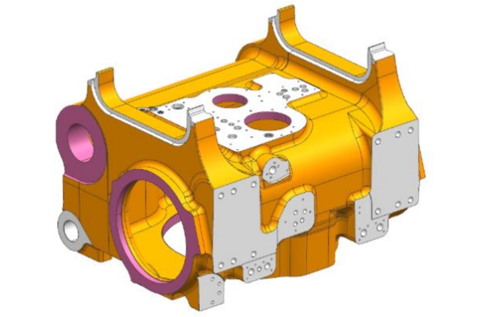
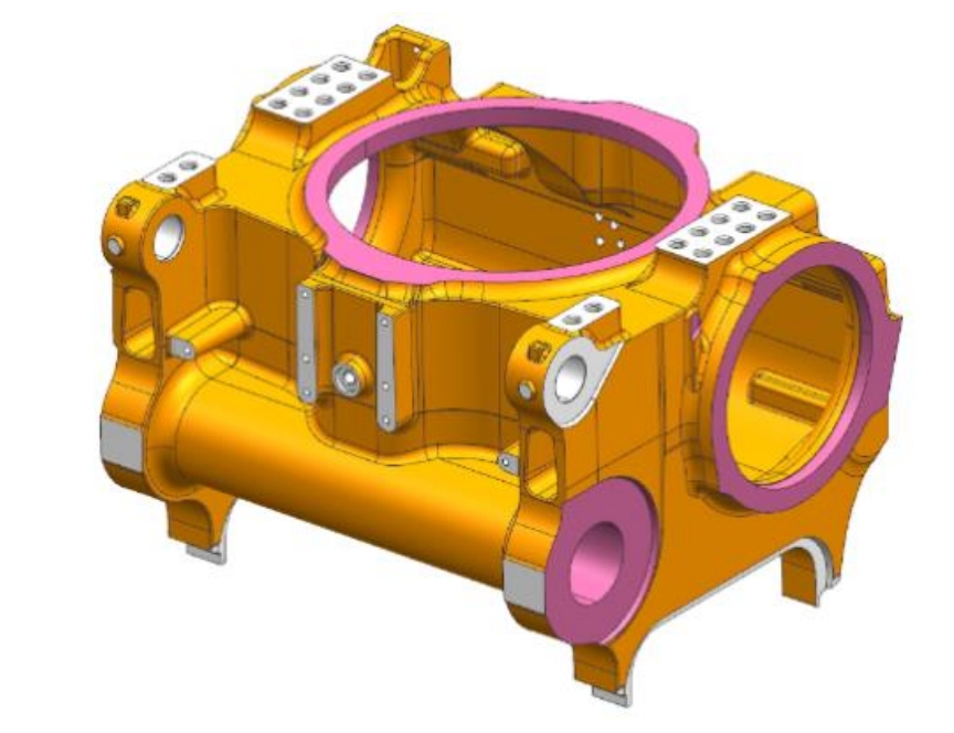
The housing steel casting features a hollow structure, with dimensions of 1510mm in length, 1265mm in width, and 1087mm in height, and a net weight of 1928kg. The casting has a maximum wall thickness of 130mm and a minimum wall thickness of 18mm. The uneven wall thickness, multiple localized protrusions, and dispersed hot spots make feeding difficult, prone to shrinkage defects. Large thin-walled areas are susceptible to deformation.
2. Original Casting Process
2.1 Introduction to the Original Casting Process
The original casting process used a pouring position with the C-shaped welding groove facing upwards. The molten steel entered through the subsidy position at the bottom box. An open gating system was employed, with ceramic pouring tubes of Φ80mm for the sprue and runner, and a variable-diameter gate brick of Φ80mm for the ingate. The ratio of the cross-sectional areas of the sprue, runner, and ingate was 1:2:4.45.
A follow-shape sand riser was placed on the cover box surface, with side risers for isolated hot spots and corresponding risers and chills for the bottom box and inner cavity. The pouring weight was 5100kg, with a process yield of 41.0%.
2.2 Deficiencies of the Original Process
During the trial production phase, several quality issues emerged:
- Each steel ladle (weighing 7500kg) could only pour one product, increasing production costs.
- The molten steel filling process was unstable, with a “waterfall” effect, leading to sand inclusion and porosity defects beyond standards.
- The heavy pouring weight (5100kg) resulted in a long pouring time of 110s, causing severe inner cavity sand burning and excessive grinding.
- Thin-walled cylindrical areas deformed, with dimensions failing to meet specifications upon three-coordinate scanning.
3. Improved Casting Process
3.1 Optimized Casting Process
The optimized casting process adopted a pouring position with the C-shaped welding groove facing downwards and a pure bottom-pour gating system. The sprue and runner used ceramic pouring tubes of Φ80mm, with four ingates of Φ70mm variable-diameter gate bricks distributed at the bottom of the casting. The ratio of the cross-sectional areas of the sprue, runner, and ingate was adjusted to 1:2:3.38, maintaining an open gating system. The pure bottom-pour system eliminated the waterfall effect during filling, ensuring smooth molten steel flow and facilitating the floating upwards of sand and impurities to the risers at the top of the casting. Risers and subsidies were optimized, with the adoption of exothermic insulation risers, subsidy shape modification, and enhanced riser feeding efficiency, reducing the pouring weight to 3400kg and increasing the process yield to 61.5%. Anti-deformation dimensions were set in large thin-walled areas, ensuring the product’s roughcast dimensions met specifications.
3.2 Improvement Effects
- The pouring weight was reduced from 5100kg to 3400kg, allowing two products per steel ladle, significantly lowering production costs.
- Molten steel entered the mold cavity through the C-shaped welding groove, resulting in a smooth filling process without entrainment of gas, and effective floating upwards of sand and impurities to the risers.
- During solidification, the risers solidified last, preventing significant shrinkage defects in the casting body. The product passed third-party radiographic inspection.
- Pouring time was reduced from 110s to 65s, drastically improving inner cavity sand burning issues and ensuring consistent casting surface quality.
- With anti-deformation dimensions, three-coordinate scanning confirmed that the roughcast dimensions were satisfactory.
4. Conclusion
- Pouring Position Determination: Place thick planes or bosses of the casting on the cover box surface to facilitate sequential solidification and riser feeding.
- Gating System for Housing Steel Castings: Use a fully open bottom-pour gating system to minimize random porosity and sand inclusion defects, enhancing internal quality.
- Exothermic Insulation Risers: Improve riser feeding efficiency, reduce pouring weight, and enhance production efficiency.
- Side Risers: Effectively address feeding difficulties in isolated hot spot areas (bosses) of housing steel castings.
- Anti-Deformation Dimensions: Effectively address deformation issues, ensuring dimensional compliance of the casting.
By meticulously analyzing and optimizing the pouring position and casting process, we significantly improved the quality and efficiency of the housing steel casting, reducing costs and enhancing product competitiveness.