
Abstract: This article focuses on the impact of preform shape on the final forging of excavator bucket teeth. It begins with an introduction to the importance of bucket teeth in excavators and the need for optimizing their manufacturing processes. The research involves analyzing the shape characteristics of bucket teeth, designing preforms, conducting numerical simulations using Deform – 3D software, and performing production trials. The results show that optimizing the preform shape can significantly improve the forging quality of bucket teeth, reducing forming difficulties and ensuring better internal metal flow and defect-free products.
1. Introduction
Excavators are crucial machinery in infrastructure projects, and bucket teeth are essential components that directly interact with hard materials like ores and rocks. Due to their high wear and tear, there is a significant demand for bucket teeth. While traditional casting methods have limitations in terms of internal defects and environmental impact, forging processes have emerged as a viable alternative. The shape of the preform plays a vital role in the final forging quality of bucket teeth, and this article aims to explore this relationship in detail.
2. Bucket Teeth Shape Analysis and Preform Design
2.1 Shape Characteristics of Bucket Teeth
The bucket teeth of a certain type of mining excavator have a complex shape. As shown in Figure 1 (not provided here but described in the original research), the forging has an elongated shape with a concave pit in the waist area, and arc-shaped protrusions on the side tops. The thickness and width vary across different sections, making it challenging to form in a single step.
2.2 Initial Preform Design and Its Limitations
A preform was initially designed for one-way closed extrusion forming. However, as shown in Figure 2 (not provided here but described in the original research), the produced bucket teeth forging had issues. Although the surface quality was relatively good and the bottom corners were filled, the arc-shaped protrusions on the “ears” did not form properly and instead formed depressions. This indicated that metal flow towards this area was difficult.
2.3 Optimized Preform Design
To address the forming difficulties, an optimized preform was designed. As shown in Figure 3 (not provided here but described in the original research), an initial arc was given to the relevant area to facilitate metal flow and reduce forming难度.
3. Mold Design and Process Scheme Formulation
3.1 Preform Mold Design
The preform mold has a relatively simple structure. The lower punch and the concave die are assembled and fixed. A heated round bar is placed inside, and the upper punch is pressed down for a specified stroke and then retracted to obtain the preform.
3.2 Final Forging Mold Design
For the final forging of bucket teeth, the key is to form the assembly hole. At least one punch is required, and if possible, two punches can be used. Considering the complex shape of the side of the bucket teeth and the need for smooth demolding after forging, a pair of vertically separable concave dies is necessary. The punch moves vertically, and the concave dies move horizontally and can actively close to prevent material jamming and flash formation during forging.
3.3 Final Forging Process Scheme
The final forging process involves placing the heated preform, closing and clamping the preform with the left and right concave dies, moving the upper outer punch down to a specified position and applying a constant pressure, and then moving the upper inner punch to the final forming position. Due to the reverse extrusion caused by the deformation of the preform, the upper outer punch may float up, and it needs to be pressed down again. After forging, the punches are retracted, the concave dies are separated, and the forging is ejected by a push rod.
4. Numerical Simulation and Production Trials
4.1 Preform Simulation
Using Deform – 3D finite element analysis software, the forging process was simulated. The initial round bar had dimensions of 75mmX162mm and was divided into 100,000 grids. The minimum grid size was 1.2mm, and the motion step length was set to 0.4mm according to the principle of using one-third of the minimum grid size. The upper punch’s downward distance was calculated based on the preform deformation, and 140 simulation steps were set. The preform was defined as plastic, and the mold material was hot forging die steel H13, defined as rigid. The preform heating temperature was set to 1150°C , the mold temperature to 300°C, the heat exchange coefficient between the preform and the mold to 5W·(m^2·°C)^-1 , and the friction coefficient to 0.3.
4.2 Final Forging Simulation and Results Analysis
4.2.1 Simulation Results of Final Forging
After re-meshing the preform based on the previous simulation results and resetting the simulation parameters, the final forging simulation was carried out. The resulting bucket teeth forging from the simulation was filled completely without obvious defects, as shown in Figure 8 (not provided here but described in the original research).
4.2.2 Analysis of Equivalent Strain
The equivalent strain cloud diagram in Deform – 3D reflects the deformation amount at each point inside the forging. As shown in Figure 9 (not provided here but described in the original research), the deformation amount of the inner wall of the assembly hole was relatively large, while that of the lower tip of the bucket teeth was relatively small.
4.2.3 Analysis of Metal Flow
The metal flow during the final forging process was analyzed using the velocity field in Deform – 3D. As shown in Figure 10 (not provided here but described in the original research), at the beginning of forging, the upper inner punch moved downwards, and the metal flow direction was consistent with the punch’s movement. As the punch stroke increased, composite extrusion occurred, and the metal flowed in different directions. Eventually, the metal flowed evenly towards the four walls of the mold until the forging was completed.
4.2.4 Analysis of Forming Load
The forming load is an important process parameter in forging. As shown in Figure 11 (not provided here but described in the original research), under the same load, the optimized preform was filled completely while the original preform did not form properly. When the forming state was the same, the mold with the optimized preform had a smaller load, indicating that the optimized preform had a more reasonable forming process.
4.3 Production Trials and Results Analysis
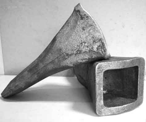
Based on the material performance tests and the simulation results of the bucket teeth forming scheme, production trials of excavator bucket teeth forgings were carried out using a 500t oil hydraulic press. Graphite lubricant was used for pre-forging, and glass lubricant was used for final forging. The final forging temperature was 1150°C. The produced bucket teeth forgings had dimensions that met the forging requirements, the assembly hole was formed well with a smooth inner wall, and the difficult-to-fill “ears” were also filled completely, as shown in Figure 12 (not provided here but described in the original research).
5. Discussion and Conclusion
5.1 Discussion
The research on the influence of preform shape on the final forging of excavator bucket teeth has provided valuable insights. By analyzing the metal flow and forming load during the forging process, it was possible to optimize the preform shape. The numerical simulation results were in good agreement with the production trial results, demonstrating the effectiveness of the simulation method in predicting the forging process.
5.2 Conclusion
In conclusion, a two-step forging process was designed based on the shape characteristics of bucket teeth. Through numerical simulation using Deform – 3D and production trials, it was found that optimizing the preform shape could effectively reduce the forming difficulty of bucket teeth and improve the forging quality. The research has important guiding significance for the selection of preform shapes, the formulation of forging processes, and the design of molds in the production of bucket teeth.
6. Future Research Directions
Future research could focus on further optimizing the preform shape for different types of bucket teeth and exploring the influence of other factors such as different materials and forging temperatures on the forging quality. Additionally, research could be extended to study the wear resistance and fatigue life of bucket teeth produced using the optimized forging process.
Table 1: Comparison of Preform Designs
| Preform Design | Advantages | Disadvantages |
|---|---|---|
| Initial Design | Good surface quality, filled bottom corners | Difficult to form arc-shaped protrusions on “ears” |
| Optimized Design | Facilitates metal flow, reduces forming, better filling of arc-shaped protrusions | – |