
The pervasive challenge of shrinkage in casting, particularly in the form of shrinkage porosity and macro-shrinkage cavities, represents a critical quality and economic bottleneck in the production of high-integrity ductile iron castings. As components become increasingly complex due to design demands such as lightweighting, the propensity for these defects escalates, necessitating a profound understanding of their formation mechanisms and the development of robust, optimized solidification control strategies. This treatise synthesizes fundamental metallurgical principles with advanced simulation-aided engineering to formulate a comprehensive methodology for eliminating shrinkage-related defects. A detailed case study on a heavy-duty truck wheel hub will serve as the practical validation of the proposed theoretical framework.
The phenomenon of shrinkage in casting is intrinsically linked to the volumetric changes a metal undergoes during its transition from liquid to solid and its subsequent cooling within the solid state. For ductile iron, this process is exceptionally complex due to its unique eutectic solidification behavior, which involves a delicate interplay between contraction and expansion phases. The total volume change, $ \Delta V_{total} $, can be conceptually modeled as the sum of three primary contributors:
$$ \Delta V_{total} \approx \Delta V_{lc} + \Delta V_{pe} + \Delta V_{ge} $$
Where:
- $ \Delta V_{lc} $ is the liquid contraction as the temperature drops from pouring to the start of solidification.
- $ \Delta V_{pe} $ is the peritectic/eutectic contraction associated with the formation of austenite from the liquid.
- $ \Delta V_{ge} $ is the graphite eutectic expansion resulting from the precipitation of graphite nodules, which has a counteracting, expansive effect.
The net result of these competing factors determines whether a sound casting or one plagued by shrinkage in casting is produced. If the expansive pressure from graphite precipitation ($ \Delta V_{ge} $) is insufficient to compensate for the preceding contractions and is not effectively harnessed by a rigid mold wall and a coherent austenitic network, internal porosity or a cavity will form. The critical factors influencing this balance are summarized in Table 1.
| Factor Category | Specific Parameter | Influence on Shrinkage Tendency |
|---|---|---|
| Material & Metallurgy | Carbon Equivalent (CE) | Higher CE increases graphite content and expansion, reducing shrinkage. |
| Nodule Count & Morphology | High, uniform nodule count promotes early and uniform expansion. | |
| Inoculation Efficiency | Effective inoculation ensures fine graphite structure, aiding feeding. | |
| Thermal & Solidification | Cooling Rate | Rapid cooling can suppress expansion, increasing shrinkage risk. |
| Section Thickness (Modulus) | Heavier sections (higher modulus) solidify last, acting as thermal centers (hot spots). | |
| Process & Design | Riser Design & Placement | Ineffective risers fail to provide liquid feed metal during critical contraction phases. |
| Gating System | Design affects temperature gradients and initial liquid distribution. | |
| Use of Chills | Accelerates local cooling, controls solidification sequence, and modifies thermal gradients. |
Two cornerstone theories guide the design of feeding systems to combat shrinkage in casting: Directional Solidification and Equivalent Solidification. Directional Solidification aims to create a continuous temperature gradient from the farthest point of the casting to the riser, ensuring the riser remains liquid longest to feed sequential shrinkage. This often requires chills to accelerate cooling in thicker areas remote from the riser. The required feeding distance, $ L_f $, can be estimated for plate-like sections as:
$$ L_f = K \sqrt{M} $$
where $ M $ is the casting section modulus (Volume/Surface Area) and $ K $ is an empirical constant dependent on alloy and mold properties.
Equivalent Solidification, particularly suited for gray and ductile irons, leverages the graphitic expansion. It posits that the riser should be designed to solidify *simultaneously* with the casting’s hot spot, not after it. The riser’s role is to supplement feeding during the liquid and early solidification contractions before the onset of useful graphite expansion. Crucially, the riser neck should solidify promptly after this feeding phase to prevent “suck-back” of liquid from the casting once expansion begins. The required riser neck modulus, $ M_{neck} $, is a key design parameter derived from the casting’s local modulus, $ M_{casting} $:
$$ M_{neck} = f \cdot M_{casting} $$
where $ f $ is a factor (typically < 1) that ensures the neck freezes at the correct time.
To transition from theory to practice, Computer-Aided Engineering (CAE) simulation is indispensable. It allows for the virtual prediction of temperature fields, solidification sequences, and the probable locations of shrinkage in casting. By solving the governing heat transfer equation numerically,
$$ \rho c_p \frac{\partial T}{\partial t} = \nabla \cdot (k \nabla T) + \dot{Q}_{latent} $$
where $ \rho $ is density, $ c_p $ is specific heat, $ k $ is thermal conductivity, and $ \dot{Q}_{latent} $ is the latent heat release rate, these tools can visualize problematic areas and enable rapid, cost-effective iterative optimization of riser and chill placement before any metal is poured.
Case Study: Process Optimization for a Heavy Truck Wheel Hub
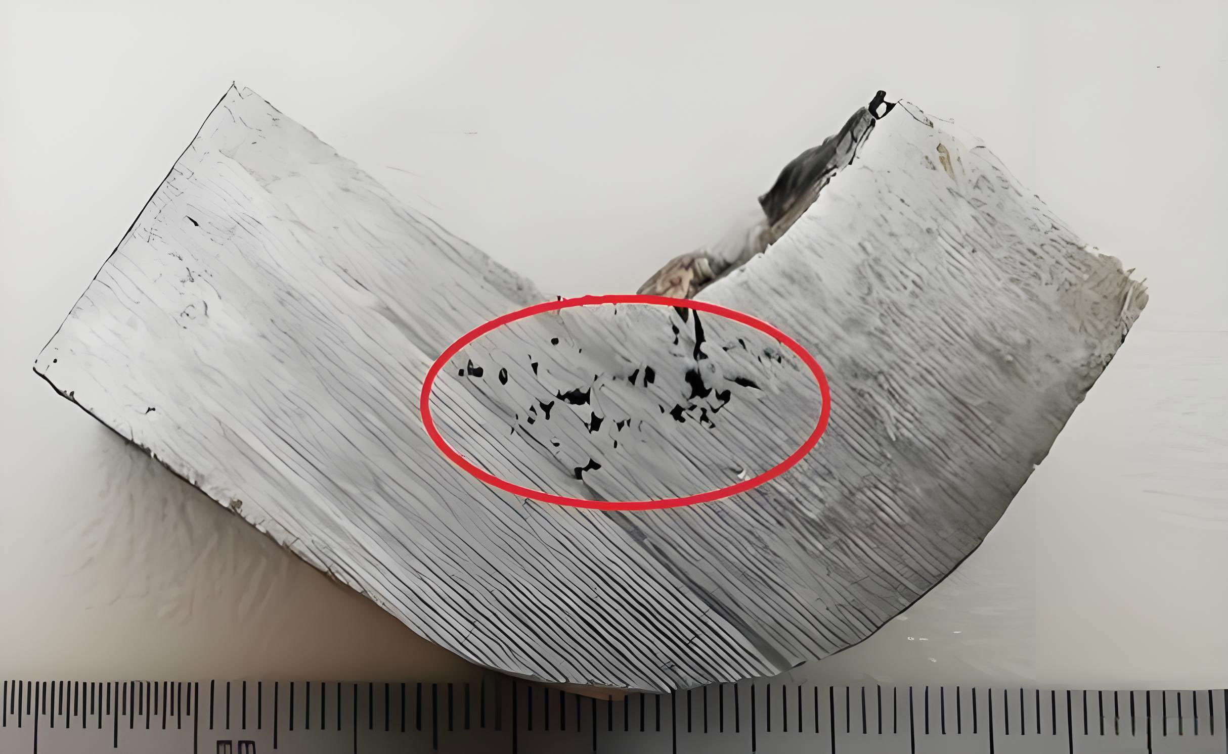
The subject component is a safety-critical ductile iron (QT600-3) wheel hub characterized by uneven wall thickness, transitioning from thin cylindrical walls (~12 mm) to thick flange and mounting boss sections (~52 mm). This geometry creates dispersed thermal centers, presenting a classic challenge for controlling shrinkage in casting. Initial production using a conventional gating and risering system yielded an unacceptable scrap rate exceeding 50% due to macro-shrinkage cavities located in the thick sections opposite the ingates.
Problem Analysis & Initial Simulation: CAE analysis of the original process revealed its fundamental flaws. The solidification sequence was highly disordered, with isolated liquid pools forming in the major hot spots. Crucially, the feeding paths from the oversized risers were prematurely sealed off by the faster solidification of thinner adjoining sections, a condition known as “liquid isolation.” This trapped liquid in the hot spot subsequently shrank without a source of feed metal, resulting in a cavity. The simulation quantitatively predicted significant shrinkage in casting, with a total solidification time $ t_{solid} $ of approximately 2355 seconds.
| Parameter | Original Process | Optimized Process | Improvement / Rationale |
|---|---|---|---|
| Riser Design Philosophy | Large, conventional side risers. | Top risers designed per Equivalent Solidification theory, placed directly over hot spots. | Ensures direct feeding to the thermal center; neck designed to freeze at correct time. |
| Chill Application | Limited use at ingates. | Strategic placement of internal chills at riser necks and key hot spots. | Reduces effective thermal modulus of hot spot, accelerates solidification, and eliminates contact heat. |
| Gating System | Simplified, slower filling. | Optimized for rapid, tranquil filling to minimize temperature loss. | Maintains higher thermal gradient, supports directional solidification. |
| Simulated Solidification Time ($ t_{solid} $) | ~2355 s | ~1453 s | 38% reduction, indicating more controlled, faster solidification. |
| Predicted Shrinkage Volume | Substantial (Shrinkage + Porosity) | Negligible | Confirmation of effective feeding and expansion utilization. |
| Solidification Sequence | Disordered, with liquid isolation. | Near-directional, from thin walls to riser. | Ensures open feeding channel until the final stage. |
The Integrated Optimization Strategy: The new design was guided by a hybrid approach. The principle of Equivalent Solidification governed the riser design—top risers were positioned directly above the identified thick sections (hot spots), with their necks carefully sized to provide feeding during contraction and then freeze. Simultaneously, the principle of Directional Solidification was enforced thermally. Internal chills were inserted at the riser neck roots and within the heavy sections. These chills served a dual purpose: 1) they effectively reduced the local modulus of the hot spot, making it solidify earlier in line with the riser neck, and 2) they created a steeper thermal gradient pointing toward the riser. The gating system was redesigned for faster filling to maintain thermal advantage.
The CAE simulation of the optimized system confirmed the efficacy of this approach. The solidification pattern showed a clear progression from the thinner, outer regions toward the risered hot spots. No liquid isolation occurred. The total solidification time was drastically reduced to 1453 seconds, and the model predicted the virtual elimination of shrinkage in casting defects.
Experimental Validation and Results
The optimized process was implemented in production using standard melting (induction furnace), ladle treatment (wire-feeding for nodularization), and molding practices. Post-fettling inspection of castings revealed sound surfaces with no visible defects. Sectioning of sample castings confirmed the internal soundness, with no macro-shrinkage cavities or significant micro-porosity in the previously problematic zones.
Statistical process tracking over a batch of 1,672 castings demonstrated a dramatic reduction in defect rate, with only 6 pieces exhibiting minor shrinkage-related issues—a scrap rate of 0.36%, down from over 50%. The residual defects were attributed to declining metal temperature in the pouring ladle during the final casts of a sequence, a factor outside the scope of the geometric optimization but important for overall process control.
Mechanical and metallurgical testing was conducted on specimens extracted from critical locations of the optimized castings. The results, compared against the stringent component specifications, are presented below.
| Property | Test Result (Optimized Casting) | Component Specification | Status |
|---|---|---|---|
| Tensile Strength | 630 MPa | > 600 MPa | Conforms |
| Yield Strength (0.2%) | 520 MPa | > 380 MPa | Conforms |
| Elongation | 7% | > 6% | Conforms |
| Hardness (HBW) | 211 | 190 – 250 | Conforms |
| Microstructure (Pearlite/Ferrite) | ~50% Pearlite | 40-70% Pearlite | Conforms |
| Nodularity / Graphite Form | Type I & II, Size 6 | > 90%, Size >6 | Conforms |
The chemical composition was also within the specified limits, ensuring the inherent material properties supported the sound solidification behavior. The successful conformance of all these properties underscores that the measures taken to eliminate shrinkage in casting did not compromise—and in fact enabled—the achievement of the required metallurgical quality.
Generalized Conclusions and Industrial Implications
This systematic investigation culminates in a validated, multi-faceted methodology for addressing the persistent problem of shrinkage in casting for complex ductile iron components:
- Fundamental Understanding is Paramount: Effective control of shrinkage in casting begins with a deep comprehension of the alloy-specific solidification dynamics, particularly the contraction-expansion sequence in ductile iron. This knowledge directly informs the choice between and application of Directional and Equivalent Solidification principles.
- Simulation as a Critical Enabler: Numerical casting simulation is not merely a validation tool but a powerful diagnostic and design platform. It allows for the precise identification of thermal centers, the visualization of solidification pathways, and the quantitative prediction of defect formation, thereby drastically reducing the time and cost associated with empirical trial-and-error.
- Hybrid Approach for Robustness: A synergistic application of Equivalent Solidification for riser design and Directional Solidification enforced via thermal modifiers (chills) provides a highly effective strategy. For components with dispersed hot spots, placing risers directly over thermal centers while using chills to manage local cooling rates and gradients ensures a controlled, feedable solidification sequence.
- Holistic Process Integration: While geometric and thermal optimization of the mold assembly is critical, ultimate success depends on its integration with consistent metallurgical practice (composition, treatment) and stable pouring parameters. The goal is to create a process window robust enough to accommodate normal production variations without initiating shrinkage in casting.
The framework established here—rooted in theory, guided by simulation, and validated by rigorous production testing—provides a replicable blueprint for foundries aiming to achieve near-zero defect rates for shrinkage in casting, enhancing product reliability, material efficiency, and overall competitiveness in the manufacture of high-performance cast components.