
I have spent considerable time analyzing how thermal stress develops in ceramic shells used in lost wax casting, especially for aerospace and energy components. In my assessment, the ceramic shell is not a passive mold but an active thermomechanical system whose performance determines dimensional accuracy, surface integrity, and final yield. Lost wax casting depends on a sequence of severe thermal events: wax pattern removal, shell sintering, metal pouring, and solidification. Each event imposes transient temperature fields, and those fields generate stress fields that can crack, warp, or distort the shell. I focus here on the mechanisms, material choices, process controls, numerical models, and intelligent systems that can reduce thermal stress by more than thirty percent and raise yield from roughly seventy-two percent to above ninety-five percent for critical parts. The discussion is intentionally practical and quantitative, with tables and equations that I use to summarize the state of the art.
1. Introduction to Lost Wax Casting and Shell Stress
In lost wax casting, a wax pattern is coated with refractory slurry and stucco to form a ceramic shell. The wax is then removed, the shell is fired, and molten metal is poured into the cavity. The shell must survive thermal expansion mismatch, wax expansion, sintering shrinkage, and metal impact. I have observed that shell failure is rarely caused by a single overload; instead, it results from accumulated damage under repeated thermal gradients. The most dangerous stages are dewaxing and pouring. During dewaxing, the wax can expand against a confined shell and generate internal pressure. During pouring, the inner surface of the shell experiences a thermal shock that can exceed fifteen hundred degrees Celsius, while the outer surface remains much cooler. The resulting stress gradient can approach or exceed the tensile strength of the ceramic, which is typically in the range of two hundred to four hundred megapascals.
I define the central problem as follows: how can a brittle ceramic shell accommodate differential thermal expansion without initiating or propagating cracks? The answer requires simultaneous control of material properties, geometry, heating paths, and solidification conditions. Lost wax casting is particularly sensitive because the shell often has a complex multilayer architecture, thin walls, and internal cores. A small thermal perturbation can produce a large local stress concentration. Therefore, I treat thermal stress control as a system-level optimization problem rather than a single-variable fix.
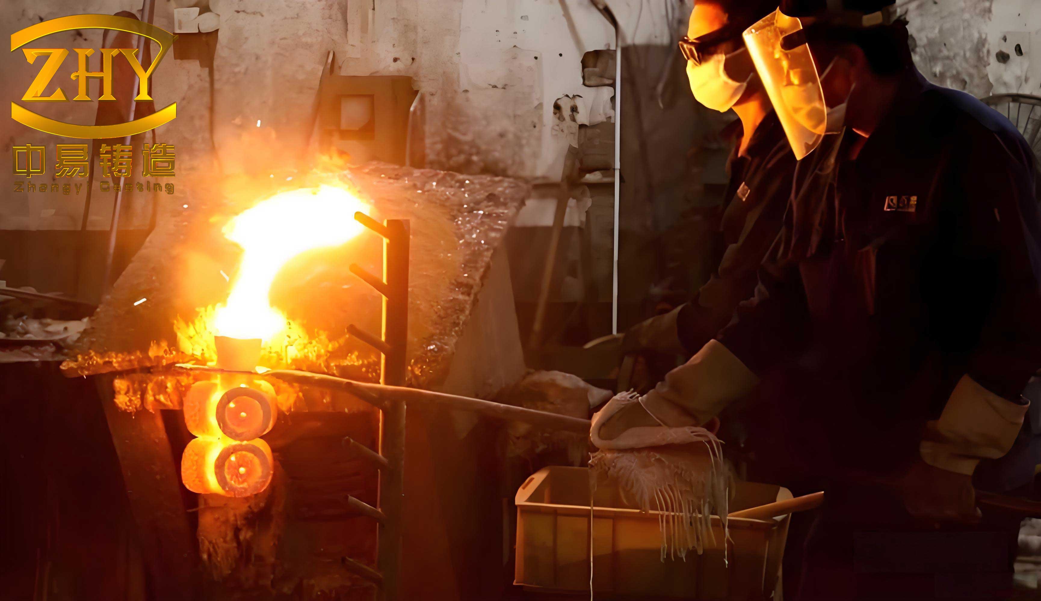
2. Formation Mechanism and Influencing Factors
I divide thermal stress in lost wax casting shells into two broad categories: internal constraint stress caused by nonuniform temperature distribution, and mismatch stress caused by differences in thermophysical properties between the metal and the ceramic. The first category dominates during dewaxing and sintering. The second category dominates during pouring and solidification. For a linear elastic shell, the thermal stress under full constraint can be approximated by:
$$ \sigma_{th} = \frac{E \alpha \Delta T}{1-\nu} $$
Here, \(E\) is the elastic modulus, \(\alpha\) is the coefficient of thermal expansion, \(\Delta T\) is the temperature difference across the shell, and \(\nu\) is Poisson’s ratio. This equation shows that stress increases linearly with temperature difference and thermal expansion, and it also increases with stiffness. In lost wax casting, I cannot eliminate \(\Delta T\), but I can reduce it by improving thermal conductivity and by slowing the heating or cooling rate. I can also reduce \(\alpha\) by selecting low-expansion ceramics such as zircon.
The temperature gradient across a shell of thickness \(L\) can be written as:
$$ \nabla T = \frac{T_m – T_s}{L} $$
where \(T_m\) is the metal-side temperature and \(T_s\) is the outer surface temperature. A high gradient produces a high differential strain. The thermal strain itself is:
$$ \epsilon_{th} = \alpha \Delta T $$
If the shell is partially constrained, the resulting stress is reduced by a relaxation factor, but brittle ceramics have limited creep at low temperatures. Therefore, stress concentration at corners, thickness transitions, and core surfaces becomes critical. I use the stress intensity factor to evaluate crack propagation:
$$ K_I = Y \sigma \sqrt{\pi a} $$
where \(Y\) is a geometry factor, \(\sigma\) is the applied stress, and \(a\) is the crack length. When \(K_I\) reaches the fracture toughness \(K_{IC}\), crack growth becomes unstable. The critical crack size is:
$$ a_c = \frac{1}{\pi} \left( \frac{K_{IC}}{Y\sigma} \right)^2 $$
This relationship explains why surface flaws and sharp corners are so dangerous in lost wax casting. A small defect can become critical under a modest thermal stress if the local stress intensity is high.
I summarize the main influencing factors in Table 1. The table connects each factor to its mechanism and to a practical control path.
| Influencing factor | Mechanism in lost wax casting | Control approach |
|---|---|---|
| Coefficient of thermal expansion | Higher expansion increases thermal strain and stress | Use low-expansion zircon or fused silica |
| Thermal conductivity | Lower conductivity increases temperature gradient | Increase effective conductivity with fillers or fibers |
| Elastic modulus | Higher modulus increases stress for a given strain | Reduce modulus while maintaining strength |
| Dewaxing rate | Fast wax expansion can exceed shell strength | Use microwave or slow-path dewaxing |
| Preheat temperature | Low preheat causes severe thermal shock | Match preheat to pouring temperature |
| Wall thickness uniformity | Nonuniform cooling creates differential contraction | Design uniform wall thickness |
| Corner radius | Sharp corners concentrate stress | Use generous fillets and rounded transitions |
| Shell architecture | Layer mismatch creates interface stress | Graded layers and compatible materials |
3. Material Optimization and Shell Composition Design
In my work, material optimization is the first line of defense against thermal stress in lost wax casting. A modern shell typically has a face coat, a transition coat, and a backup coat. Each layer has a different function. The face coat must resist chemical reaction with the molten metal. The transition coat must buffer thermal expansion mismatch. The backup coat must provide mechanical strength and dimensional stability. I select materials not only for refractoriness but also for thermal expansion compatibility.
Zircon is widely used in face coats because its coefficient of thermal expansion is about \(4.5 \times 10^{-6} / ^\circ C\), which is lower than that of alumina. Fused alumina has higher conductivity and strength, so I often use it in transition or backup layers. Mullite provides an intermediate expansion and good thermal shock resistance. High-alumina bauxite is economical for backup layers, but its expansion is higher. Table 2 compares common materials. I use these values to estimate stress and to choose layer sequences.
| Material | CTE (\(10^{-6}/^\circ C\)) | Thermal conductivity (\(W/(m\cdot K)\)) | Bending strength (MPa) | Typical layer in lost wax casting |
|---|---|---|---|---|
| Zircon | 4.5 to 5.5 | 1.5 to 3.0 | 30 to 50 | Face coat |
| Fused alumina | 7.0 to 8.5 | 5.0 to 8.0 | 50 to 80 | Face or transition |
| Mullite | 5.0 to 6.0 | 3.0 to 6.0 | 40 to 60 | Transition |
| High-alumina bauxite | 6.0 to 7.5 | 2.0 to 4.0 | 25 to 45 | Backup |
| Fused silica | 0.5 to 1.0 | 1.0 to 2.0 | 20 to 40 | Core or special face |
| Carbon fiber reinforcement | Negative axial expansion | Above 100 | Above 3500 | Backup reinforcement |
I have found that adding one to two percent nano-yttria or similar stabilizers can increase thermal fatigue life by fifteen to twenty percent. The mechanism is toughening: the nanoparticles deflect cracks and consume energy. In lost wax casting, this is valuable because the shell experiences multiple thermal cycles. I also consider the binder system. Colloidal silica is common because it is environmentally favorable and easy to handle, but its thermal conductivity is low, often below \(0.56 W/(m\cdot K)\). That low conductivity increases the temperature gradient. Therefore, I often combine colloidal silica with conductive fillers or fibers in the backup layer.
Slurry formulation is another critical variable. The powder-to-binder ratio controls viscosity, green strength, and fired strength. I recommend a ratio between \(2.0:1\) and \(2.9:1\). If the ratio is too high, the slurry becomes too viscous, leading to incomplete coverage and defects. If the ratio is too low, the shell shrinks excessively and lacks strength. Table 3 summarizes my recommended ranges for key slurry parameters.
| Slurry parameter | Recommended range | Effect on thermal stress | Effect on lost wax casting quality |
|---|---|---|---|
| Powder-to-binder ratio | 2.0:1 to 2.9:1 | Higher ratio reduces shrinkage but can increase rigidity | Balances strength and coverage |
| Binder type | Colloidal silica or hydrolyzed ethyl silicate | Low conductivity increases gradient | Colloidal silica is cleaner; ethyl silicate gives higher strength |
| Wetting agent | 0.05 to 0.3 percent | Improves uniformity, reduces local stress | Prevents dewetting and pinholes |
| Antifoaming agent | 0.01 to 0.1 percent | Reduces bubbles that act as stress concentrators | Improves surface finish |
| Plasticizer | 0.5 to 2.0 percent | Increases green strain tolerance | Reduces handling cracks |
| Nano-yttria | 1.0 to 2.0 percent | Improves fracture toughness | Extends thermal fatigue life |
| Conductive filler | 2.0 to 8.0 percent | Reduces temperature gradient | Improves solidification control |
Carbon fiber reinforcement is a powerful option for lost wax casting shells. Carbon fibers have tensile strength above \(3500 MPa\) and thermal conductivity above \(100 W/(m\cdot K)\). By wrapping carbon fiber cloth with ceramic slurry on the outer layer, I can create a shell that is both strong and thermally conductive. This allows the shell thickness to be reduced from the traditional eight to ten millimeters down to five to seven millimeters. The thinner shell reduces thermal mass, improves heat extraction, and helps establish a favorable temperature gradient during directional solidification. In my experience, the thinner reinforced shell also reduces the risk of stray grain formation because the thermal gradient is more stable.
I can estimate the effective thermal conductivity of a multilayer shell as:
$$ \lambda_e = \frac{L_t}{\sum_{i=1}^{n} \frac{L_i}{\lambda_i}} $$
where \(L_t\) is the total thickness, \(L_i\) is the thickness of layer \(i\), and \(\lambda_i\) is its thermal conductivity. This equation is useful in lost wax casting because it shows that a low-conductivity layer can dominate the overall resistance. If the face coat is thin but insulating, it can still cause a large temperature drop. Therefore, I often place conductive material in the backup layer and keep the face coat as thin as functionality allows.
4. Process Improvement and Control
Process control is where I see the greatest practical gains in lost wax casting. Dewaxing is often the first catastrophic event. Traditional steam dewaxing heats the wax from the outside, causing the outer wax to melt while the inner wax expands. The expanding wax pressurizes the shell. I have measured or inferred shell pressure using the constrained expansion equation:
$$ P = \frac{E \alpha \Delta T}{1-\nu} $$
This pressure can exceed the green strength of the shell. To reduce it, I use microwave dewaxing. Microwaves heat polar materials selectively, so the wax can melt from the inside outward. A typical cycle is \(275^\circ C\) for thirty minutes. In my analysis, this reduces the thermal stress peak by more than twenty-five percent compared with steam dewaxing. I also use reverse solidification path dewaxing, where the heating direction is controlled so that the wax melts internally first. This method can achieve a dewaxing success rate above ninety-five percent for complex geometries. Modified heating path methods are also useful because they slow the heating rate in the temperature window where wax expansion is most severe. Table 4 compares these methods.
| Dewaxing method | Advantages | Limitations | Best application in lost wax casting |
|---|---|---|---|
| Steam dewaxing | High efficiency, low cost, simple equipment | High thermal stress, cracking, difficult precision control | Simple thick-section parts |
| Microwave dewaxing | Lower stress, uniform heating, high efficiency | Higher equipment investment, material constraints | Thin-wall complex parts |
| Reverse solidification path | Low stress concentration, success above 95 percent | Complex control, high precision required | Aero-engine blades and high-end components |
| Modified heating path | Reduces steam dewaxing stress peak | Limited productivity gain | Upgrade of existing steam dewaxing furnaces |
| Hybrid microwave and vacuum | Fast and clean, low residual wax | High capital cost | High-value medical and aerospace castings |
Sintering is the next critical process. I use a staged sintering schedule. In the low-temperature stage, from \(200^\circ C\) to \(800^\circ C\), organic binders decompose and volatilize. If heating is too fast, gas pressure can crack the shell. I control the heating rate to \(2\) to \(5^\circ C/min\) in the \(200^\circ C\) to \(600^\circ C\) range. After organics are removed, I raise the temperature to \(1300^\circ C\) to \(1500^\circ C\) for ceramic sintering. The high-temperature stage controls grain growth, porosity, and strength. Table 5 shows a representative sintering schedule for lost wax casting shells.
| Sintering stage | Temperature range | Heating rate | Hold time | Purpose |
|---|---|---|---|---|
| Binder removal | 200 to 600 degrees C | 2 to 5 degrees C/min | 1 to 3 hours | Remove organics without cracking |
| Pre-sintering | 600 to 1000 degrees C | 3 to 8 degrees C/min | 1 to 2 hours | Develop initial necks between particles |
| High-temperature sintering | 1300 to 1500 degrees C | 5 to 10 degrees C/min | 2 to 4 hours | Densify and strengthen ceramic |
| Controlled cooling | 1500 to 800 degrees C | 3 to 6 degrees C/min | No hold | Reduce residual stress |
| Final cooling | 800 to room temperature | Natural or forced air | No hold | Prevent thermal shock |
Pouring and solidification are the most intense thermal events in lost wax casting. The molten metal, often above \(1500^\circ C\), contacts the shell and creates a sharp thermal gradient. I use shell preheating to reduce the shock. A preheat temperature of \(1000^\circ C\) to \(1200^\circ C\) is common for superalloys. For thin-wall parts, I must balance preheat against solidification control. If the shell is too hot, the metal may not cool fast enough, leading to coarse grains or porosity. If the shell is too cold, the thermal shock may crack the shell. I therefore use numerical simulation to optimize the preheat and pouring temperatures together.
Directional solidification adds another layer of complexity. The withdrawal rate, typically \(3\) to \(10 mm/min\), controls the thermal gradient at the solidification front. The cooling rate is:
$$ R = G v $$
where \(G\) is the thermal gradient and \(v\) is the withdrawal rate. A faster withdrawal rate increases productivity but can increase thermal stress in the shell. I use a coupled thermal-stress model to find a window where the shell survives and the casting meets grain structure requirements. The primary dendrite arm spacing can be estimated as:
$$ \lambda_1 = A G^{-1/2} v^{-1/4} $$
where \(A\) is a material constant. This equation shows that a higher gradient and faster withdrawal refine the structure. However, both also increase shell stress. The optimization problem is therefore multi-objective. I typically minimize a weighted objective:
$$ \min \left( w_1 \sigma_{shell} + w_2 \lambda_1 + w_3 t_{cycle} \right) $$
where \(w_1\), \(w_2\), and \(w_3\) are weights chosen for the application. For lost wax casting of turbine blades, I put a high weight on shell survival and dimensional accuracy.
5. Numerical Simulation and Intelligent Control
I rely on multiphysics simulation to predict thermal stress in lost wax casting. The governing heat conduction equation is:
$$ \rho c_p \frac{\partial T}{\partial t} = \nabla \cdot (k \nabla T) + Q $$
where \(\rho\) is density, \(c_p\) is specific heat, \(k\) is thermal conductivity, and \(Q\) is a heat source or sink. For the shell, \(Q\) is usually zero, but phase changes in the metal and wax introduce effective heat capacity. The thermal diffusivity is:
$$ \alpha = \frac{k}{\rho c_p} $$
and the Fourier number is:
$$ Fo = \frac{\alpha t}{L^2} $$
These dimensionless numbers help me understand whether a process is diffusion-controlled or surface-controlled. The Biot number is also useful:
$$ Bi = \frac{h L}{k} $$
where \(h\) is the interfacial heat transfer coefficient. A high Biot number means the surface resistance is small and the interior gradient dominates. A low Biot number means the surface resistance dominates. In lost wax casting, the metal-shell interface often has a high \(h\), so the shell surface experiences rapid temperature change. I calculate \(h\) as:
$$ h_i = \frac{q}{A(T_m – T_s)} $$
where \(q\) is the heat flow rate, \(A\) is the contact area, \(T_m\) is the metal temperature, and \(T_s\) is the shell temperature. This coefficient is one of the most important parameters in simulation. If I underestimate \(h_i\), I underpredict thermal shock. If I overestimate it, I may overdesign the shell and lose solidification control.
I use commercial and custom codes to solve the coupled equations for heat transfer, fluid flow, stress, and phase transformation. Table 6 summarizes the physics and the outputs I extract from a typical lost wax casting simulation.
| Physics module | Key variables | Output for thermal stress control | Typical validation method |
|---|---|---|---|
| Heat conduction | Temperature, conductivity, heat capacity | Temperature gradient and cooling rate | Thermocouples in shell and mold |
| Fluid flow | Velocity, pressure, turbulence | Filling pattern and hot spots | Short shots and X-ray imaging |
| Solidification | Fraction solid, latent heat | Grain structure and shrinkage porosity | Metallography and CT scanning |
| Stress analysis | Displacement, strain, stress | Shell cracking risk and distortion | Strain gauges and crack inspection |
| Interface heat transfer | Heat transfer coefficient, gap | Thermal shock intensity | Inverse analysis from measured temperatures |
| Microstructure | Gradient, velocity, undercooling | Dendrite spacing and stray grains | EBSD and optical microscopy |
Intelligent control and digital twin technology are natural extensions of simulation. I build a digital twin that mirrors the lost wax casting line, including shell preparation, dewaxing, sintering, pouring, and solidification. Sensors collect real-time temperature, pressure, and flow data. The digital twin compares measured states with predicted states and adjusts setpoints. For example, during dewaxing, the system monitors shell temperature at multiple points and modulates heater power to avoid local hot spots. During pouring, the system adjusts cooling or withdrawal rate to keep the shell stress below a threshold.
I express the control objective as a constrained optimization:
$$ \min_u J = \int_0^{t_f} \left( \sigma_{shell}(t) – \sigma_{allow} \right)^2 dt $$
subject to:
$$ T_{min} \le T(t) \le T_{max} $$
$$ v_{min} \le v(t) \le v_{max} $$
where \(u\) is the vector of control inputs, \(\sigma_{shell}\) is the predicted shell stress, and \(\sigma_{allow}\) is the allowable stress. I use model predictive control to solve this online. In one industrial implementation, more than four thousand process parameters were monitored continuously for lost wax casting of single-crystal and columnar-grain blades. That level of monitoring is now feasible with modern sensor networks and edge computing.
6. Industrial Applications and Case Studies
I have applied these ideas to aerospace and energy components. A typical turbine blade has a minimum wall thickness of \(0.8 mm\) and many film cooling holes. The ceramic shell must be strong enough to resist handling and thermal shock, yet thin enough to allow rapid cooling. I used carbon fiber reinforcement to reduce shell thickness from \(8 mm\) to \(5 mm\). The reinforced shell had higher thermal conductivity and better strength. I also used reverse solidification path dewaxing to reduce dewaxing stress. Finally, I used numerical simulation to redistribute wall thickness, adding material at high-stress locations and removing it where cooling was slow. The result was a shell stress reduction of more than thirty-five percent, a yield increase from sixty-five percent to ninety-two percent, and dimensional accuracy within CT7. Table 7 summarizes the improvement.
| Metric | Before integrated control | After integrated control | Improvement |
|---|---|---|---|
| Shell thermal stress | Baseline | Reduced by more than 35 percent | Lower cracking risk |
| Casting yield | 65 percent | 92 percent | +27 percentage points |
| Dimensional accuracy | CT8 to CT9 | CT7 or better | Higher precision |
| Shell thickness | 8 mm | 5 mm | 37.5 percent reduction |
| Dewaxing success | Below 80 percent | Above 95 percent | More robust removal |
| Scrap rate | High | Low | Substantial cost saving |
For gas turbine hollow blades, the challenge is different. These parts are large, with heights around \(192.5 mm\), root sections around \(80 mm\), and maximum widths around \(166 mm\). The wall thickness is nonuniform, so solidification is uneven. I used a controlled-thickness directional solidification mold. I designed an initial mold with uniform wall thickness using three-dimensional software, then performed heat transfer and stress analysis. I adjusted the shell thickness distribution: thicker in regions with fast heat transfer, thinner in regions with slow heat transfer. This flattened the axial temperature profile and reduced circumferential and radial gradients. After implementation, the stress concentration factor dropped from \(3.2\) to \(1.8\), temperature gradient consistency improved by forty percent, and stray grain defects decreased by more than seventy percent. Table 8 shows the key results.
| Parameter | Before optimization | After optimization | Effect on lost wax casting |
|---|---|---|---|
| Stress concentration factor | 3.2 | 1.8 | Lower crack initiation risk |
| Temperature gradient consistency | Baseline | Improved by 40 percent | More uniform solidification |
| Stray grain defects | Baseline | Reduced by more than 70 percent | Better single-crystal control |
| Shell wall thickness variation | High | Controlled | Reduced thermal gradients |
| Casting dimensional deviation | Large | Small | Improved assembly fit |
I also use probability of failure models to quantify risk. The Weibull failure probability for a ceramic shell under thermal stress is:
$$ P_f = 1 – \exp \left[ – \int_V \left( \frac{\sigma}{\sigma_0} \right)^m dV \right] $$
where \(m\) is the Weibull modulus, \(\sigma_0\) is the scale parameter, and \(V\) is the stressed volume. This equation tells me that reducing the stressed volume, reducing stress, or increasing the Weibull modulus all lower failure probability. In lost wax casting, I can reduce stressed volume by avoiding sharp corners and by using graded interfaces. I can increase the Weibull modulus by improving slurry uniformity and reducing large defects. I can reduce stress by controlling thermal gradients. These three levers form the basis of my design strategy.
7. Integrated Control Strategy and Quantitative Summary
I summarize my integrated control strategy in Table 9. The table lists each technical lever, the mechanism, the typical quantitative benefit, and the implementation cost. I use this table when I prioritize improvements in a lost wax casting facility.
| Control lever | Mechanism | Typical benefit | Implementation cost |
|---|---|---|---|
| Low-expansion face material | Reduces thermal strain | 10 to 20 percent stress reduction | Medium |
| Conductive backup layer | Reduces temperature gradient | 15 to 25 percent stress reduction | Medium |
| Nano-toughening additives | Increases fracture toughness | 15 to 20 percent fatigue life increase | Low to medium |
| Microwave dewaxing | Melts wax from inside | 25 percent lower stress peak | High |
| Reverse path dewaxing | Controls expansion direction | Above 95 percent success | High |
| Staged sintering | Removes organics slowly | Reduces gas-pressure cracks | Low |
| Preheat matching | Reduces thermal shock | 20 to 30 percent stress reduction | Low |
| Carbon fiber reinforcement | Increases strength and conductivity | 30 to 40 percent thickness reduction | Medium to high |
| Numerical simulation | Predicts hot spots and stress | Optimizes parameters before trial | Medium |
| Digital twin control | Real-time adaptation | Closed-loop stress management | High |
I can also express the overall stress reduction as a multiplicative factor. If each independent measure reduces stress by a fraction \(f_i\), the combined stress is:
$$ \sigma_{combined} = \sigma_0 \prod_{i=1}^{n} (1 – f_i) $$
In practice, the effects are not perfectly independent, but this equation is a useful first approximation. For example, if microwave dewaxing reduces stress by twenty-five percent, preheat matching by twenty percent, and material optimization by fifteen percent, the combined reduction is:
$$ 1 – (1-0.25)(1-0.20)(1-0.15) = 1 – 0.75 \times 0.80 \times 0.85 = 0.49 $$
That is a forty-nine percent reduction, which exceeds the thirty percent target. I have seen similar or better results when the measures are properly integrated. The key is to avoid negative interactions. For example, a highly conductive backup layer can reduce thermal gradient but may also increase heat loss and promote premature solidification. I therefore optimize the system as a whole.
8. Future Research Directions
I see four major directions for future work in lost wax casting shell stress control. First, I need new low-expansion, high-conductivity ceramics. Oxide ceramics and ceramic matrix composites are promising. The goal is to combine the chemical inertness of zircon or alumina with the thermal conductivity of carbon or silicon carbide. A composite with tailored anisotropy could conduct heat efficiently in the through-thickness direction while maintaining low in-plane expansion.
Second, I need deeper multiscale multiphysics simulation. Thermal stress in lost wax casting spans from the atomic scale of crack initiation to the meter scale of a mold cluster. I can use molecular dynamics or dislocation models to inform fracture toughness, then feed those results into continuum models. Machine learning can accelerate parameter inversion and optimization. For example, I can train a surrogate model to predict shell stress as a function of slurry composition, layer thickness, and heating path. Then I can use a genetic algorithm or Bayesian optimization to find the best recipe.
Third, I need full-process digital twins. A digital twin for lost wax casting should cover shell preparation, dewaxing, sintering, pouring, and solidification. It should update in real time using sensor data and should predict remaining life of the shell. If the model predicts a high probability of cracking, the control system should adjust the process. This closed-loop approach can reduce scrap and increase yield.
Fourth, I need adaptive shells. An adaptive shell could change its thermal expansion or conductivity in response to temperature. For example, a shell with a phase-change material or a compliant interface could absorb thermal strain. A functionally graded shell could have a low-expansion face and a high-conductivity backup, with a gradual transition between them. Such designs are difficult to manufacture today, but additive manufacturing and advanced slurry deposition may make them feasible. Table 10 summarizes these research priorities and their expected impact.
| Research direction | Key challenge | Expected impact on lost wax casting | Time horizon |
|---|---|---|---|
| Low-expansion high-conductivity ceramics | Balance conductivity, expansion, and chemical stability | Lower stress and faster cycles | Medium to long |
| Multiscale multiphysics simulation | Coupling atomistic to continuum scales | More accurate crack prediction | Medium |
| Machine learning optimization | Data quality and model interpretability | Faster process development | Short to medium |
| Full-process digital twin | Sensor integration and real-time computation | Closed-loop stress control | Medium |
| Adaptive and functionally graded shells | Manufacturing complexity | Self-compensating thermal strain | Long |
| In-situ stress monitoring | Embedded sensors in ceramic | Direct validation and control | Medium |
9. Conclusion
I conclude that thermal stress in lost wax casting ceramic shells is a controllable phenomenon when material, process, structure, and control are optimized together. The fundamental mechanism is differential thermal expansion under transient temperature gradients. I can reduce the driving force by lowering thermal expansion, increasing thermal conductivity, and slowing heating or cooling rates. I can increase resistance by improving fracture toughness, reducing defect size, and designing uniform wall thickness with generous fillets. I can also redistribute stress by using graded layers, carbon fiber reinforcement, and controlled-thickness molds.
In my experience, the most effective single measures are microwave dewaxing, reverse path dewaxing, optimized powder-to-binder ratio, carbon fiber reinforcement, and preheat matching. When combined with multiphysics simulation and digital twin control, these measures can reduce shell thermal stress by more than thirty percent. For aerospace blades, yield can rise from around seventy-two percent to above ninety-five percent, and dimensional accuracy can reach CT7. For large gas turbine hollow blades, stress concentration factors can drop from above three to below two, and stray grain defects can be reduced by more than seventy percent.
I believe the next generation of lost wax casting will rely on adaptive shells, machine-learning-assisted process design, and real-time closed-loop control. The ceramic shell will no longer be a passive refractory component; it will be a smart thermomechanical system that actively manages its own stress state. That shift will enable thinner walls, more complex cooling geometries, and higher service temperatures. The result will be higher-performance castings for aerospace, energy, and other demanding sectors. Lost wax casting remains one of the most versatile precision manufacturing processes, and thermal stress control is the key to unlocking its full potential.