
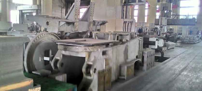
In this article, we detail the trial production of a critical equipment roll, originally fabricated as a welded component and now converted to a nodular cast iron large casting. The roll weighed approximately 19 tons, with a maximum wall thickness of 320 mm and a minimum of 55 mm, demanding uniform wall thickness throughout. Material specifications adhered to EN-GJS-400-18U-RT per DIN EN 1563:2012-3, requiring extensive non-destructive testing and mechanical validation via attached test blocks and body sampling. This large casting posed significant challenges due to its size, thick sections, and stringent quality controls. Our approach integrated computer simulations, optimized gating and feeding systems, and advanced melting techniques to achieve defect-free production. The success provides a scalable model for future large casting projects.
The structural complexity of the roll, with dimensions of φ2000 mm × 4500 mm, necessitated meticulous casting design to prevent defects like shrinkage porosity, slag inclusions, and graphite degeneration. Uniform wall thickness was critical for dynamic balancing; deviations could lead to operational failures. For this large casting, we employed CAD modeling and solidification simulation to predict thermal gradients and optimize riser and chill placements. The gating system featured a bottom-pour design with a ceramic sprue (φ120 mm) to ensure smooth filling. Key ratios were set as \( F_{\text{sprue}} : F_{\text{runner}} : F_{\text{ingate}} = 1 : 2 : 1.2 \), with a calculated pouring time of 120 seconds. Chills combined with risers enhanced feeding efficiency, particularly at thick junctions like the upper flange. The simulation equation for solidification time, based on Chvorinov’s rule, guided our design:
$$ t = k \cdot \left( \frac{V}{A} \right)^2 $$
where \( t \) is solidification time, \( k \) is a mold constant, \( V \) is volume, and \( A \) is surface area. This minimized hot spots in the large casting.
For the molding process, we used furan resin-bonded sand to ensure high strength and dimensional accuracy, vital for the large casting‘s 100% ultrasonic inspection requirements. The mold height exceeded 7 m, including risers, so a three-box system was adopted for ease of handling. Core assembly focused on vertical alignment to maintain uniform cavity dimensions. Reinforcement measures, such as steel plate welding at parting lines, countered high metallostatic pressure and prevented mold distortion. Resin content was increased to boost rigidity, reducing risks like veining or sand expansion in the large casting. Coating with zircon-based alcohol paint minimized burn-on defects.
Melting chemistry was pivotal for achieving the desired ferritic microstructure in this large casting. We followed a “high-carbon, low-silicon, low-manganese, low-sulfur, low-phosphorus, minimal rare earth and magnesium” strategy to enhance graphite nodularity and mechanical properties. Carbon equivalent (\( CE \)) was tightly controlled to avoid graphite flotation, using the formula:
$$ CE = C + \frac{Si}{3} $$
Target ranges were derived from empirical data on thick-section castings. High-purity pig iron and selected scrap steel ensured low trace elements (\(\sum \text{trace elements} \leq 0.06\%\)). Key compositional controls are summarized in Table 1.
| Element | Target Range | Rationale |
|---|---|---|
| C | 3.60–3.70 | Promotes graphite nucleation; prevents flotation at high CE |
| Si | 2.20–2.40 | Limits ferrite embrittlement and chunk graphite formation |
| Mn | ≤ 0.30 | Reduces pearlite and microsegregation |
| P | ≤ 0.030 | Minimizes phosphide eutectic at grain boundaries |
| S | ≤ 0.020 | Enhances nodularity and reduces slag |
| Mg | 0.030–0.050 | Optimizes graphite spheroidization with minimal shrinkage |
| RE | ≤ 0.020 | Avoids abnormal graphite in thick sections |
| CE | 4.40–4.60 | Balances fluidity and defect prevention |
Treatment involved a hybrid yttrium-based heavy rare earth and light rare earth inoculant (1.3–1.4% addition) via the sandwich method. Pouring temperature was maintained at 1350–1360°C. Three-stage inoculation with 75# FeSi and high-Ca/Ba inoculants (total 0.8–1.0%) refined graphite morphology. The inoculation efficiency (\( \eta \)) can be expressed as:
$$ \eta = \frac{N_{\text{graphite}}}{A} \times 100\% $$
where \( N_{\text{graphite}} \) is graphite count per unit area and \( A \) is area, ensuring high nodularity in the large casting.
Production outcomes validated our methods. The large casting exhibited uniform wall thickness (55\(^{+5}_{-3}\) mm), passing ultrasonic, magnetic particle, and penetrant tests. Attached test blocks (200 mm × 200 mm × 200 mm) and body samples from roll ends met EN-GJS-400-18U-RT specifications. Mechanical properties from test blocks and body samples are compared in Table 2.
| Sample Type | Tensile Strength (MPa) | Yield Strength (MPa) | Elongation (%) | Hardness (HB) |
|---|---|---|---|---|
| Attached Test Block | 371 | 262 | 23 | 140 |
| Upper Body Sample | 352 | 245 | 16 | 138 |
| Lower Body Sample | 386 | 249 | 21 | 141 |
Metallography showed >95% nodularity and ferrite content >80%, with graphite size grade 5–6. No evidence of shrinkage, slag, or degenerate graphite was found, confirming the efficacy of our process for large casting applications.
This trial demonstrates that robust simulation, precise chemistry, and multi-stage inoculation enable reliable production of high-integrity large casting components. The methodologies can be adapted for batch production of similar heavy-section rolls, reducing reliance on welded alternatives. Future work will focus on scaling these techniques for even larger castings, reinforcing the role of integrated design in advancing foundry capabilities.