
In my extensive career as a non-destructive testing (NDT) specialist, I have frequently encountered challenging scenarios during magnetic particle inspection (MPI) of critical components made from spheroidal graphite cast iron. This material, commonly known as ductile iron, is prized for its excellent mechanical properties, such as high strength and good ductility, due to its unique microstructure featuring graphite nodules in a ferritic or pearlitic matrix. However, these very microstructural characteristics can lead to ambiguous magnetic particle indications that closely mimic genuine defects like cracks, posing significant interpretation difficulties. Through detailed investigations, I have developed methodologies to distinguish non-relevant displays from true flaws, ensuring component integrity and reliability. This article delves into a comprehensive analysis of non-relevant indications in spheroidal graphite cast iron, leveraging microscopic examination, hardness testing, and spectroscopic data to elucidate their origins and provide practical guidance for NDT practitioners.
Spheroidal graphite cast iron, such as the QT700-2 grade, is widely used in aerospace and automotive applications due to its balanced combination of strength and toughness. The material’s microstructure typically consists of graphite spheroids embedded in a matrix of pearlite and ferrite, which influences its magnetic properties. During MPI, which relies on detecting magnetic flux leakage at discontinuities, the inherent microstructural inhomogeneities in spheroidal graphite cast iron can produce non-relevant indications. These are magnetic particle accumulations that do not correspond to detrimental defects but arise from factors like compositional segregation, porosity, or graphite distribution anomalies. My focus here is on a case study involving an oil separator disc component, where such indications were observed, and the systematic approach taken to resolve them.
The oil separator disc, fabricated from QT700-2 spheroidal graphite cast iron, underwent routine fluorescent magnetic particle inspection during aircraft maintenance. The component operates under rotational friction and hydraulic pressure up to 2 MPa, with a design life of approximately 5000 hours. During inspection, multiple anomalous magnetic indications appeared on the working surface, exhibiting point-like, linear, and irregular shapes reminiscent of cracks. These indications measured 2–4 mm in length and were distributed both radially and axially. Initial assessments ruled out false indications: the particles did not flow upon component movement, remained after gentle washing with suspension, and reappeared upon re-magnetization after cleaning. This prompted further investigation using complementary NDT methods and microscopic analysis.
To ascertain the nature of these indications, I first performed fluorescent penetrant testing (PT) and X-ray radiography. PT revealed no surface-open defects, while radiography showed no significant porosity or cracks. This preliminary evidence suggested that the indications were likely related to microstructural features rather than gross defects. Consequently, I proceeded with detailed microscopic examination of sections extracted from the indication areas, employing scanning electron microscopy (SEM), energy-dispersive X-ray spectroscopy (EDS), metallographic analysis, and microhardness testing.
The chemical composition and mechanical properties of the QT700-2 spheroidal graphite cast iron are foundational to understanding its behavior. As per standard specifications, the composition and key parameters are summarized below:
| Element | C | Si | Mn | S | P |
|---|---|---|---|---|---|
| Content | 3.08–3.30 | 2.49–3.13 | 0.55–0.61 | 0.017–0.022 | 0.045–0.052 |
| Matrix | Microstructure | Tensile Strength σb (MPa) | Yield Strength σ0.2 (MPa) | Elongation δ (%) | Hardness (HB) |
|---|---|---|---|---|---|
| Pearlite | Graphite + Pearlite + Ferrite | ≥700 | ≥420 | ≥2 | 225–305 |
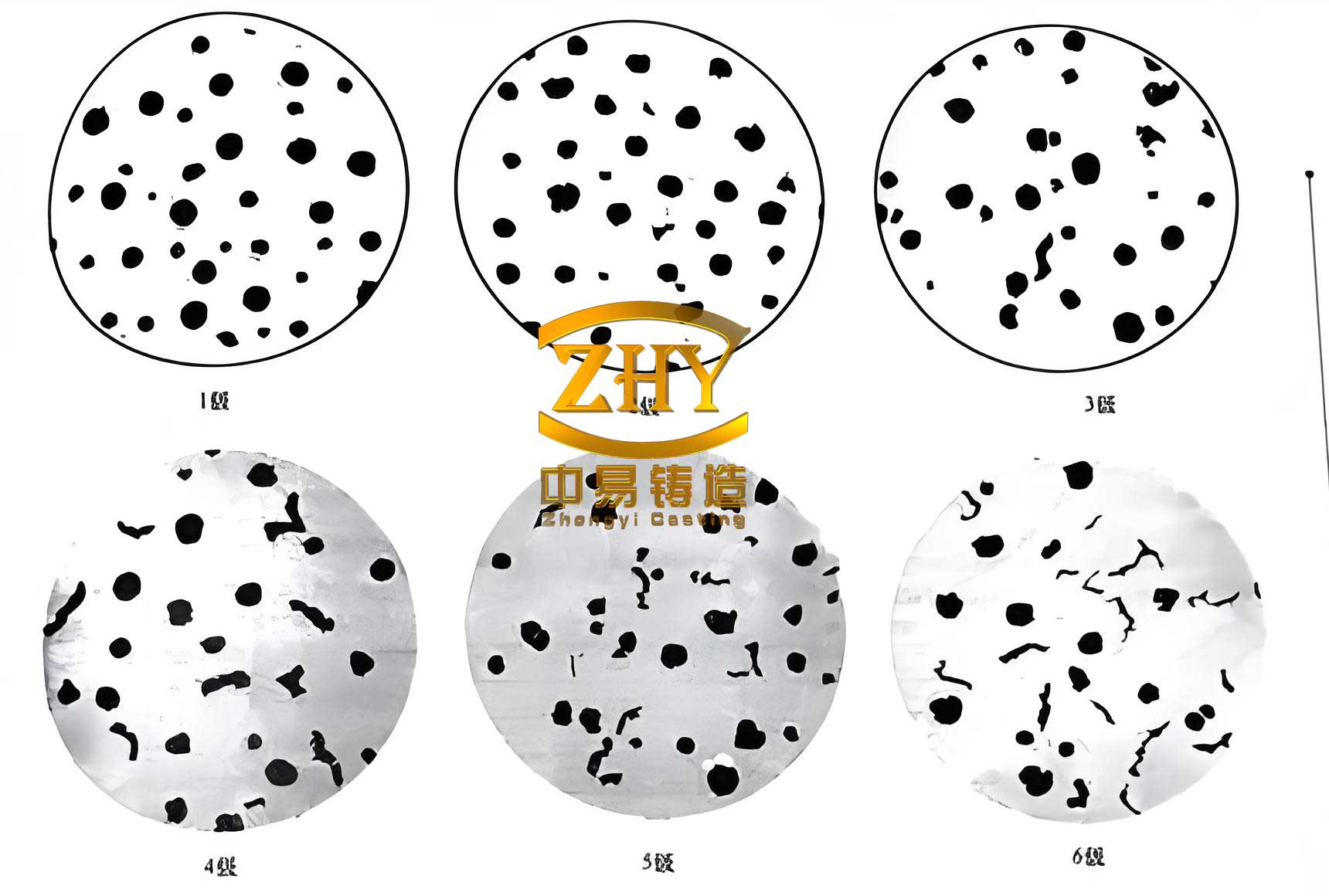
SEM analysis of the indication zones revealed several key features. In Region I, linear cracks extending from the surface inward were observed, accompanied by pit-like defects. These linear and pit features contained particulate fillers, identified as graphite particles, and exhibited no significant microstructural difference from the surrounding matrix except for localized higher ferrite content. This suggested that these were casting-related imperfections, possibly due to poor spheroidization of graphite, where filler material detached during service, creating superficial linear openings. Porosity was also noted, with irregularly shaped voids showing rough internal surfaces and particulate contaminants, but no evidence of corrosive elements upon EDS analysis, indicating they were shrinkage porosities from the casting process.
In Regions II and III, surface scratches and embedded particulate matter were detected, likely from handling or machining. Regions IV and V displayed irregular, curved linear graphite distributions and porosity, consistent with casting anomalies. EDS analysis was conducted on various features to determine elemental composition, as summarized below:
| Sample | C | O | Mg | Al | Si | Mn | Fe | Other Elements |
|---|---|---|---|---|---|---|---|---|
| Porosity Spot 1 | 36.32 | 10.69 | 2.82 | 1.39 | 2.33 | – | 45.57 | Na, P, Cl, K |
| Porosity Spot 2 | 41.56 | 21.25 | 2.22 | 2.30 | 4.25 | – | 26.15 | Na, K, Ti |
| Matrix | 5.59 | – | – | – | 4.39 | 0.52 | 89.50 | – |
| Embedded Particulate | 8.02 | 4.84 | – | – | 0.45 | – | 13.95 | Ni, Cu, Sn, Pb |
| Linear Graphite Zone 1 | 84.04 | 11.00 | 0.48 | 0.21 | 0.40 | – | 3.44 | Ti |
| Linear Graphite Zone 2 | 16.51 | 18.96 | 6.22 | 2.89 | 4.71 | – | 44.39 | S, Ce |
The EDS data confirm that the linear indications are rich in carbon, typical of graphite, and contain trace elements like magnesium and silicon, indicative of spheroidizing agents or inclusions from casting. The embedded particulate was a copper-based alloy, likely foreign contamination. These findings align with the notion that non-relevant displays in spheroidal graphite cast iron often stem from microstructural heterogeneities introduced during manufacturing.
Metallographic examination of sections cut radially and axially through the indication areas further clarified the microstructure. The base material exhibited a mixture of blocky ferrite and pearlite with dispersed spherical graphite nodules. However, in the indication zones, linear and pit defects were filled with graphite particles, and the adjacent matrix showed slightly higher ferrite content. This microstructural variation can affect magnetic permeability, leading to flux leakage and particle accumulation. The magnetic permeability contrast between different phases can be approximated by the formula: $$\Delta \mu = \mu_{\text{matrix}} – \mu_{\text{inclusion}}$$ where $\mu_{\text{matrix}}$ is the permeability of the ferritic-pearlitic matrix and $\mu_{\text{inclusion}}$ is that of graphite or pores. Since graphite is non-magnetic ($\mu_{\text{graphite}} \approx 1$), while ferrite and pearlite have higher permeability, this difference can generate detectable indications even without true cracks.
Microhardness testing was performed to assess material consistency. Using a Vickers hardness tester with a 0.5 kgf load, measurements were taken and converted to Brinell hardness (HB) according to GB/T 1172-1999. The conversion can be approximated by the empirical relation: $$HB \approx \frac{HV}{0.95} $$ for this material range, though exact values depend on the standard tables. The results are tabulated below:
| Test Location | Vickers Hardness (HV0.5) | Brinell Hardness (HB) |
|---|---|---|
| Position I | 293.65 | 288.65 |
| Position II | 306.31 | 300.31 |
| Position III | 289.91 | 284.91 |
| Position IV | 280.01 | 276.01 |
| Average | 292.47 | 287.47 |
The hardness values fall within the specified range of 225–305 HB, confirming that the material meets mechanical requirements and that the indications are not due to gross hardening or softening anomalies.
Synthesizing these analyses, I concluded that the magnetic particle indications on the spheroidal graphite cast oil separator disc were non-relevant displays caused by micro-shrinkage porosity and irregular graphite distributions resulting from casting process variations. The spheroidal graphite cast iron’s inherent microstructure, with its graphite nodules and potential segregation, acts as magnetic discontinuities. During MPI, when the component is magnetized, the magnetic flux lines concentrate at these inhomogeneities, causing particle buildup. This phenomenon is particularly pronounced in spheroidal graphite cast iron due to the stark permeability difference between the metallic matrix and graphite. The fundamental equation for magnetic flux leakage can be expressed as: $$\Phi = \int_A \mathbf{B} \cdot d\mathbf{A}$$ where $\Phi$ is the magnetic flux, $\mathbf{B}$ is the magnetic flux density, and $A$ is the area. At locations with lower permeability, such as graphite clusters or pores, $\mathbf{B}$ diverges, creating leakage fields that attract magnetic particles.
Beyond this case, non-relevant displays are common in other materials like precipitation-hardening and martensitic stainless steels, often due to residual austenite, delta-ferrite, or compositional banding. For spheroidal graphite cast iron, however, the primary culprits are casting defects like poor spheroidization, slag inclusions, or porosity. To mitigate interpretation errors, I recommend a systematic approach for evaluating ambiguous indications in spheroidal graphite cast iron components:
First, eliminate false indications by verifying particle mobility, cleanliness, and reproducibility. Then, consider the indication characteristics: non-relevant displays in spheroidal graphite cast iron often appear as diffuse, irregular lines following metal flow lines or as clustered spots, unlike the sharp, linear features of true cracks. If uncertainty persists, employ supplementary NDT methods. For instance, penetrant testing can confirm surface openness, while radiography or ultrasonic testing may reveal subsurface features. In cases where the component allows, gentle grinding to remove superficial layers (within tolerance) followed by re-inspection can help; if indications disappear, they likely stem from near-surface microstructure.
Additionally, adjusting MPI parameters can be informative. Reducing magnetizing current may cause non-relevant indications to fade, as they often require lower field strengths to manifest compared to real cracks. This relates to the magnetic field intensity $H$ and the material’s magnetization curve. For spheroidal graphite cast iron, the optimal magnetizing current $I$ can be estimated using: $$I = \frac{H \cdot L}{N}$$ where $L$ is the component length and $N$ is the number of turns in a coil, but practical adjustments should follow standard guidelines.
Microstructural analysis remains the gold standard. When possible, sectioning and examining indication areas under a microscope can definitively identify features like graphite alignment, porosity, or inclusions. For spheroidal graphite cast iron, etching with reagents like nital reveals the ferrite-pearlite distribution and graphite morphology. Establishing a reference library of micrographs for common non-relevant displays in spheroidal graphite cast iron aids future comparisons.
Furthermore, understanding the casting process is crucial. Spheroidal graphite cast iron production involves inoculation and spheroidization treatments to control graphite shape; deviations can lead to vermicular or flake graphite, which are more prone to causing magnetic indications. The nodularity ratio, defined as the percentage of graphite particles with aspect ratios close to 1, affects mechanical and magnetic properties. A simple formula to assess nodularity is: $$Nodularity = \frac{N_{\text{spherical}}}{N_{\text{total}}} \times 100\%$$ where $N_{\text{spherical}}$ is the count of spherical nodules and $N_{\text{total}}$ is the total graphite count. Lower nodularity often correlates with increased non-relevant indications.
In terms of material science, the magnetic behavior of spheroidal graphite cast iron can be modeled using effective medium theory, where the composite permeability $\mu_{\text{eff}}$ is a function of the matrix permeability $\mu_m$ and graphite volume fraction $f_g$: $$\mu_{\text{eff}} = \mu_m \left(1 – f_g\right) + \mu_g f_g$$ with $\mu_g \approx 1$. This illustrates how higher graphite content reduces overall permeability, enhancing flux leakage at nodules.
To summarize, non-relevant magnetic particle indications in spheroidal graphite cast iron are predominantly artifacts of microstructural heterogeneity from casting. They do not compromise component integrity if properly identified. Key takeaways include: rigorous multi-method analysis, familiarity with material-specific patterns, and procedural adaptations during inspection. For spheroidal graphite cast iron, maintaining strict process control during melting and casting minimizes these indications. As NDT technology advances, techniques like digital image analysis and machine learning may aid in automating distinction, but foundational knowledge remains essential.
In conclusion, my investigation into the oil separator disc exemplifies how a holistic approach combining NDT, metallography, and spectroscopy resolves ambiguous indications. Spheroidal graphite cast iron, with its complex microstructure, demands careful interpretation to avoid unnecessary rejections. By disseminating such insights, I aim to enhance reliability in industries relying on this versatile material, ensuring safety and performance without undue conservatism. Future work could explore quantitative models linking graphite morphology to magnetic indication severity, further refining standards for spheroidal graphite cast iron inspection.