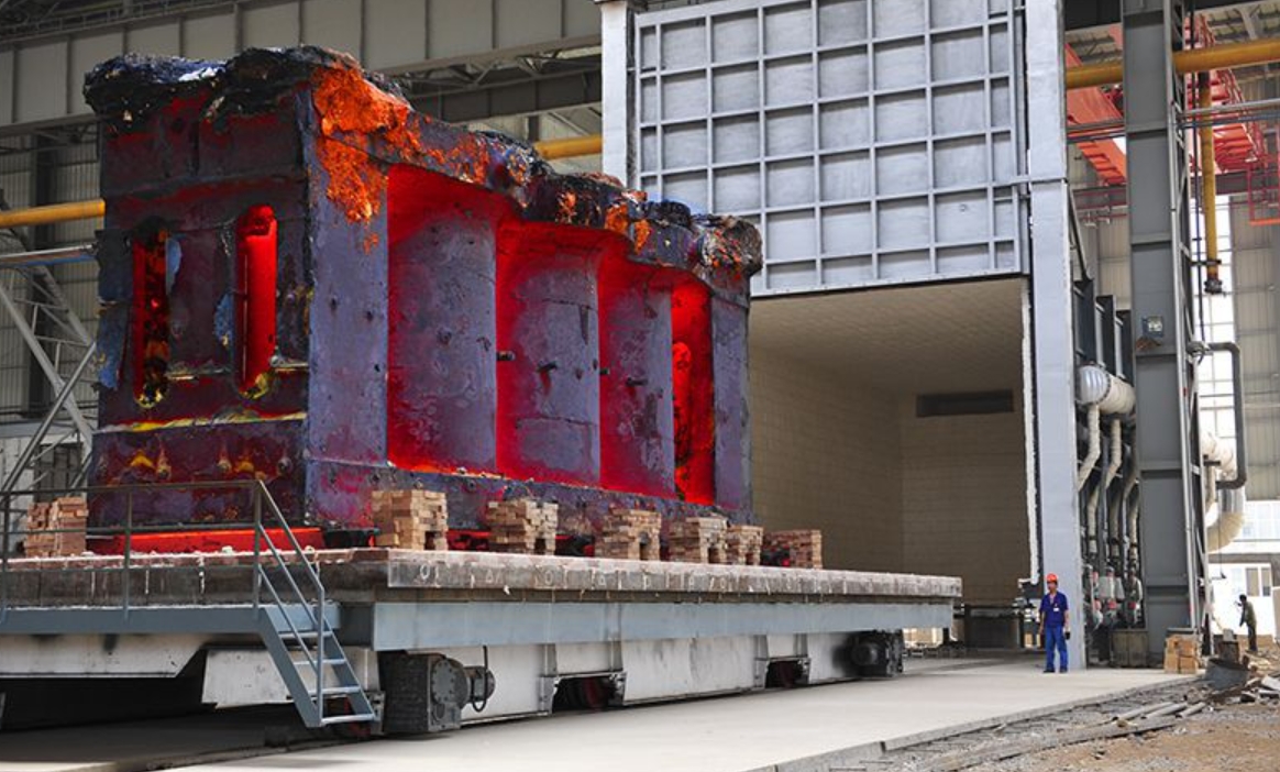
In production practice, the duration of pouring time directly impacts multiple quality factors in large castings. For complex thin-walled castings, excessively long pouring can cause defects like misruns, cold shuts, porosity, and sand inclusions. Conversely, for thick-section large castings, overly short pouring leads to shrinkage defects, high residual stresses, and mold deformation. This critical relationship necessitates precise calculation methodologies for effective pouring time.

Over 30 pouring time formulas exist for gravity casting, but those specific to large castings lack standardization. Common limitations include:
- Inconsistent wall thickness considerations
- Limited applicability across casting geometries
- Overreliance on weight-only parameters
- Material-specific restrictions
Deficiencies in Conventional Formulas
Traditional calculations for large castings exhibit significant limitations across material categories:
| Material | Typical Formula | Critical Deficiencies |
|---|---|---|
| Gray Iron | $$ t = S \sqrt{G} $$ | Excessive times for thick sections (>100mm), porosity risks |
| Ductile Iron | $$ t = (2.5-3.5) \sqrt[3]{G} $$ | Ignores wall thickness, wide coefficient range (2.5-3.5) |
| Steel | $$ t = \frac{G}{nq} $$ | Requires pre-determined gating area, unsuitable for thick sections |
| Aluminum | $$ t = S \sqrt[3]{G} $$ | Excessively fast pouring for thick-section large castings |
| Copper | $$ t = S \sqrt{G} $$ | Double weight dependency, ignores wall thickness |
Universal limitations include poor adaptation to multi-gating systems, absence of differentiation between effective pouring and feeding phases, and inadequate handling of specialized pouring methods like stopper-controlled systems.
Effective Pouring Time Concept
We distinguish two phases:
- Effective pouring time (t): Metal entry until mold cavity fills to highest contour
- Feeding time: Subsequent phase for riser feeding and compensation
Precise control of effective pouring time is essential for defect prevention in large castings, while feeding time remains context-dependent.
Unified Calculation Formula
The proposed effective pouring time formula addresses material properties, geometry, and gating configurations:
$$ t = f \left( \sqrt{G} + \sqrt[3]{15\delta \cdot G} \right) \cdot \left( \frac{2}{3} \right)^{n-1} $$
Where:
- \( t \): Effective pouring time (seconds)
- \( G \): Casting weight excluding feeders/risers (kg)
- \( \delta \): Dominant wall thickness, typically minimum (mm)
- \( n \): Gating system groups or ladles used (max n=3)
- \( f \): Material coefficient
Material coefficients account for fluidity, pouring temperature, and density variations:
| Material | \( f \) Value |
|---|---|
| Gray Iron | 1.0 |
| Ductile Iron, Steel, White Iron | 0.60–0.80 |
| Copper/Zinc Alloys | 1.10–1.20 |
| Aluminum/Magnesium Alloys | 1.50–1.60 |
The gating correction factor \( \left( \frac{2}{3} \right)^{n-1} \) adapts to various production scenarios:
- Single gating (\( n=1 \)): No correction
- Dual gating (\( n=2 \)): 33% time reduction
- Triple gating/stoppers (\( n=3 \)): 56% time reduction
Validation Across Large Casting Types
The formula demonstrates ±10% accuracy across diverse large castings:
Gray Iron Applications
| Casting Description | Weight (t) | Thickness (mm) | Actual Time (s) | Calculated Time (s) | Rise Velocity (mm/s) |
|---|---|---|---|---|---|
| Cooling Box | 3.68 | 30 | 100–110 | 89 | 10.4 |
| Large Plate | 7.87 | 30 | 60 | 56 | 6.3 |
| Machine Frame | 14.5 | 25 | 135 | 108 | 20.0 |
Ductile Iron and Steel Applications
| Casting Description | Material | Weight (t) | Actual Time (s) | Calculated Time (s) |
|---|---|---|---|---|
| Flywheel | Ductile Iron | 1.3 | 44–50 | 62 |
| Support Base | Ductile Iron | 5.0 | 100 | 83 |
| Furnace Hopper | Steel | 15.3 | 85 | 63 |
| Hydraulic Frame | Steel | 90.0 | 71.4 | 84 |
Non-Ferrous Applications
| Casting Description | Material | Weight (t) | Actual Time (s) | Calculated Time (s) |
|---|---|---|---|---|
| Aluminum Housing | ZL101 | 0.12 | 21 | 27 |
| Curved Surface | ZL114 | 1.1 | 64 | 56 |
| Propeller | Copper Alloy | 1.55 | 79 | 72 |
Implementation Guidelines
For specialized large castings:
- Plates/Stopper Systems: Treat as \( n+1 \) for acceleration effect
- Combined Systems: For dual gates with one stopper, use \( n=2.5 \)
- Extreme Geometries: Adjust \( t \) by ±10% based on height-to-width ratio
Conclusion
This unified approach eliminates coefficient ambiguities while accommodating:
- All major casting alloys through \( f \) values
- Diverse gating configurations via \( (2/3)^{n-1} \)
- Geometric variability through combined \( \sqrt{G} \) and \( \sqrt[3]{\delta G} \) terms
The formula demonstrates robust applicability across large casting types, from massive steel frames to complex aluminum housings, providing foundries with a scientifically grounded calculation tool that replaces empirical estimation. Production data confirms ±10% accuracy for weights exceeding 20 tons and thicknesses up to 600mm, establishing a new standard for effective pouring time determination.
