
In the evolving landscape of modern manufacturing, the foundry industry faces increasing pressure to adopt greener, more efficient processes. Among these, V-method molding, also known as vacuum molding, has emerged as a pivotal technology, particularly for producing high-quality machine tool castings. From my extensive involvement in designing and implementing casting facilities, I have witnessed firsthand how this process transforms production paradigms. This article delves into the application of V-method molding lines in a dedicated machine tool casting workshop, exploring the technical intricacies, economic benefits, and environmental advantages. The focus is on a large-scale project aimed at producing over 20,000 tons annually of critical components like bed ends, counterweights, and disk bodies—all integral to machine tool systems. Through detailed analysis, including tables and formulas, I will elucidate why V-method molding is becoming the cornerstone for sustainable machine tool casting production.
The core appeal of V-method molding lies in its simplicity and eco-efficiency. Unlike traditional methods that rely on chemical binders, it uses a vacuum to hold dry, unbonded sand in place around a plastic film-coated pattern. This eliminates the need for resins, reduces volatile organic compound emissions, and allows for near-total sand reclamation. For machine tool castings, which demand dimensional accuracy, smooth surface finishes, and structural integrity, V-method molding offers a compelling solution. It minimizes machining allowances, thereby reducing material waste and cost—a critical factor in the competitive machine tool industry. My experience in this project underscored how automation of V-method lines can further enhance productivity, making it ideal for high-volume production of standardized machine tool components.
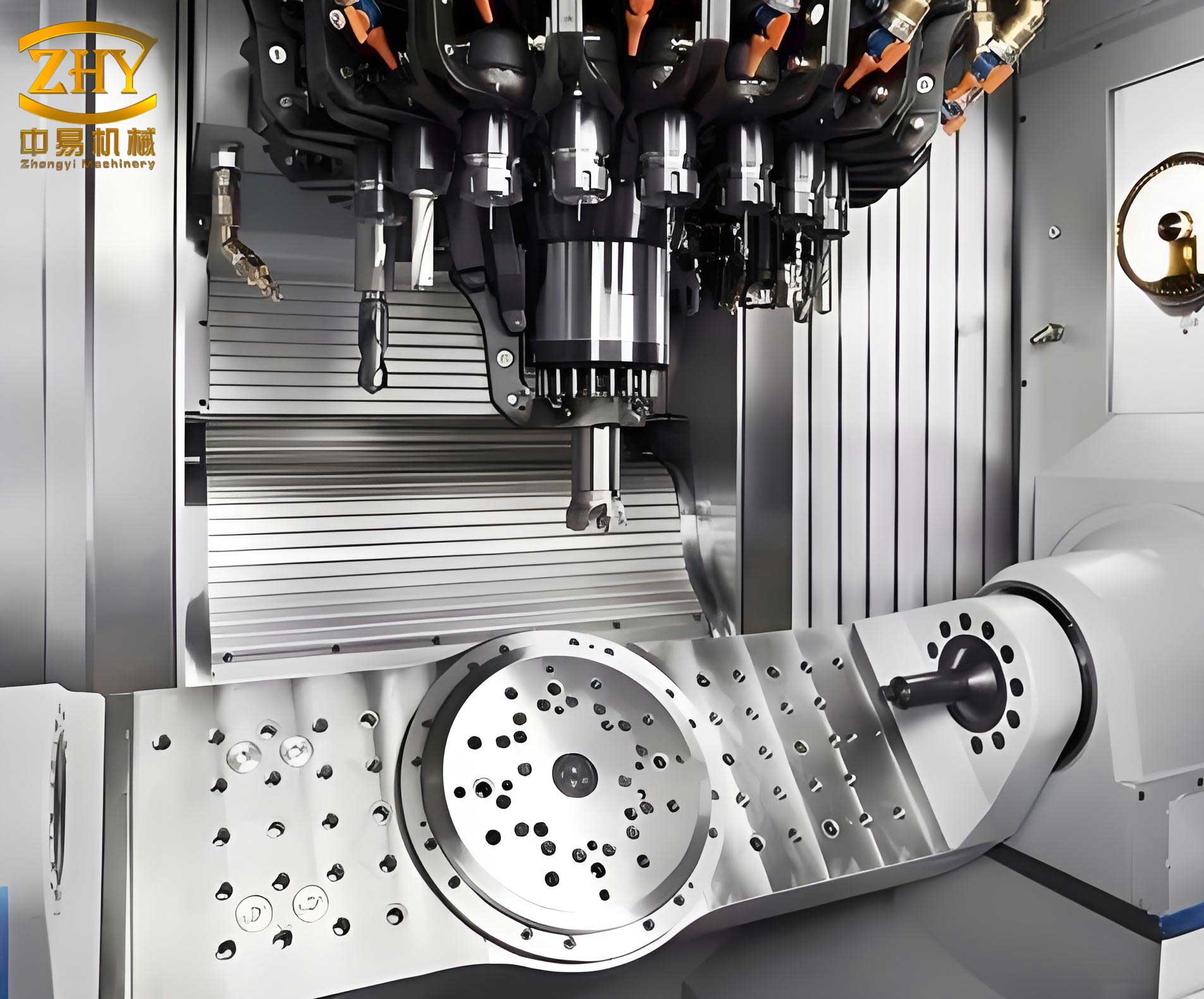
The project centered on establishing a new V-method casting workshop with an annual capacity of 20,000 tons. This facility was designed to specialize in machine tool castings, including disk bodies (225,000 pieces), bed ends (45,000 pieces), and counterweights (16,000 pieces). Such volumes necessitate a highly automated, continuous flow production system. The workshop layout was meticulously planned to optimize logistics, dividing into functional zones: melting, molding line, sand handling, and cleaning. Material transport is facilitated by overhead cranes, electric flat cars, and forklifts, ensuring seamless movement from melting to dispatch. This design minimizes handling time and maximizes equipment utilization, which is essential for maintaining the high throughput required for machine tool casting production.
To provide a clear overview of the workshop layout, the following table summarizes the key zones and their functions:
| Zone Code | Functional Area | Primary Activities |
|---|---|---|
| I | Lower Mold Making Area | Initial molding stages for lower halves |
| II | Core Setting Station | Placement and inspection of cores |
| III | Upper Mold Making Area | Molding processes for upper halves |
| IV | Pouring Station | Molten metal pouring into molds |
| V | Cooling Station | Controlled solidification of castings |
| VI | Sand Fall & Treatment | Shakeout, sand screening, and cooling |
| VII | Dust Removal System | Air pollution control |
| VIII | Circulating Water System | Cooling water management |
| IX | Vacuum System | Central vacuum supply for molding |
| X | Pattern Storage Area | Storage and maintenance of patterns |
| XI | Core Making Area | Manufacture of sand cores |
| XII | Melting Zone | Iron melting and holding |
The heart of the operation is the automated V-method molding line, configured as two interconnected loops for upper and lower molds. Each loop comprises twelve stations, with eleven patterns circulating simultaneously to achieve a design rate of 15 complete molds per hour. The mold dimensions are standardized at 2500 mm × 1500 mm × 500/450 mm, accommodating a maximum casting weight of 1.1 tons per box. This setup is specifically tailored for the repetitive production of machine tool castings, ensuring consistency and quality. The line integrates advanced equipment such as film heaters, rain sand feeders, vibratory compaction tables, coating dryers, and robotic manipulators for mold handling. The entire process, from film coating to mold closing, is sequenced to minimize downtime and labor intervention.
A detailed breakdown of the molding line stations and their functions is presented below:
| Station Number | Process Step | Key Actions |
|---|---|---|
| 1 | Film Heating & Drapping | Thermal softening and application of plastic film to pattern |
| 2 | Coating Application | Spraying or brushing of refractory coating |
| 3 | Coating Inspection | Quality check for uniformity and defects |
| 4 | Sand Box Placement | Positioning of flask over coated pattern |
| 5 | Drying | Initial drying of applied coating |
| 6 | Pattern Transfer | Movement to next station via conveyor |
| 7 | Secondary Drying | Further drying to ensure coating integrity |
| 8 | Drying Inspection | Final check before sand filling |
| 9 | Sand Filling, Compaction & Sealing | Rain sand addition, vibration, leveling, and back film application |
| 10 | Mold Inspection | Verification of sand fill and vacuum seal |
| 11 | Pattern Stripping | Vacuum release and pattern removal from mold |
| 12 | Transfer to Next Stage | Mold moved to core setting or closing line |
The melting section employs medium-frequency induction furnaces for melting, holding, and composition adjustment of iron. This choice aligns with local energy availability and provides precise control over metal quality. Charge materials—including pig iron, scrap steel, and returns—are weighed using electromagnetic scales and loaded via charging cars. For quality assurance, a direct-reading spectrometer is used for rapid chemical analysis. This ensures the molten iron meets the stringent specifications required for durable machine tool castings, which often involve complex stresses and wear resistance.
After molding and pouring, the castings undergo a series of post-processing steps. Shakeout is performed on vibratory conveyors, where sand falls through grates for recycling. The machine tool castings are then transported to cleaning areas for removal of gates and risers, shot blasting, welding repair, grinding, and final inspection. A stress-relief annealing may be applied based on the specific requirements of the machine tool component. Finally, a primer coat is applied before dispatch to machining workshops. This streamlined flow is crucial for maintaining the high-volume output necessary for machine tool casting production.
Core making, though minimal for many machine tool castings in this project, combines manual methods with hot-box core shooters. The process involves coating core boxes with film, filling with sand, and curing via heat to form precise internal geometries. This flexibility allows for the production of complex cores when needed, without compromising the overall efficiency of the V-method line.
Key technical parameters of the V-method line are summarized in the table below, highlighting the engineering specifications that enable efficient machine tool casting production:
| Parameter | Value | Unit |
|---|---|---|
| Design Molding Rate | 15 | complete molds/hour |
| Flask Internal Dimensions | 2500 × 1500 × 500/450 | mm |
| Max. Casting Weight per Flask | 1.1 | tons |
| Average Casting Weight per Flask | 0.54 | tons |
| Pouring Station Capacity | 48 | positions |
| Core Setting Station Capacity | 8 | positions |
| Minimum Cooling Time | 416 | minutes |
| Compressed Air Pressure | >0.45 | MPa |
| Water Supply Pressure | >0.18 | MPa |
| Vacuum Line Negative Pressure | -0.045 to -0.07 | MPa |
| Total Installed Power | ~1960 | kW |
| Free Air Consumption | 2300 | m³/hour |
| Crane Rail Height | 10.8 | meters |
The economic and environmental benefits of V-method molding can be quantified through several formulas. For instance, the sand reclamation rate, a critical metric for sustainability, is defined as:
$$ R_s = \frac{S_r}{S_t} \times 100\% $$
where \( R_s \) is the sand reclamation rate, \( S_r \) is the amount of sand recovered and reused, and \( S_t \) is the total sand consumption. In V-method molding, \( R_s \) typically exceeds 95%, significantly reducing new sand purchase and waste disposal costs. This high reclamation rate is especially advantageous for large-scale machine tool casting production, where sand usage is substantial.
Another important formula relates to production efficiency. The theoretical hourly output of castings in tons can be expressed as:
$$ P_h = N_m \times W_a \times \eta $$
where \( P_h \) is the hourly production output (tons/hour), \( N_m \) is the number of molds produced per hour (15 for this line), \( W_a \) is the average casting weight per mold (0.54 tons), and \( \eta \) is the operational efficiency factor (often 0.85-0.95 accounting for downtime). For this line, the nominal output is:
$$ P_h = 15 \times 0.54 \times 0.90 = 7.29 \text{ tons/hour} $$
This high throughput underscores the capability of V-method lines to meet the demands of mass production for machine tool castings.
Furthermore, the reduction in machining allowance due to the superior surface finish of V-method castings translates into direct cost savings. The material saving per casting can be approximated as:
$$ M_s = \rho \times (V_t – V_v) $$
where \( M_s \) is the mass of material saved (kg), \( \rho \) is the density of the casting material (e.g., 7.2 g/cm³ for cast iron), \( V_t \) is the volume of material removed in traditional casting after machining, and \( V_v \) is the volume removed in V-method casting. For a typical machine tool casting, this saving can be 5-15%, which, when multiplied by thousands of pieces, yields substantial economic benefits.
The vacuum system is central to the process, and its performance can be modeled using the ideal gas law under negative pressure conditions. The required vacuum pump capacity can be estimated by:
$$ Q = \frac{V \times \Delta P}{t} $$
where \( Q \) is the volumetric flow rate (m³/s), \( V \) is the volume of the mold cavity and sand interstices (m³), \( \Delta P \) is the pressure difference between atmospheric and vacuum (Pa), and \( t \) is the time to achieve the desired vacuum level (s). In practice, the system is designed to maintain a steady-state vacuum of -0.045 to -0.07 MPa across multiple molds simultaneously, ensuring mold integrity during handling and pouring.
From an environmental perspective, the elimination of organic binders avoids the generation of harmful byproducts like formaldehyde and phenol, which are common in resin sand processes. The environmental impact reduction can be partially expressed through a simplified emission avoidance formula:
$$ E_a = M_b \times C_e $$
where \( E_a \) is the avoided emissions (kg of pollutants), \( M_b \) is the mass of binder saved annually, and \( C_e \) is the emission factor per unit binder. For a workshop producing 20,000 tons of machine tool castings, the binder saving can exceed 500 tons per year, leading to significant reductions in air pollution.
In conclusion, the adoption of automated V-method molding lines represents a transformative step for the foundry industry, particularly in the realm of machine tool casting production. This project demonstrates that through careful design, integration of advanced automation, and optimization of process parameters, it is possible to achieve high-volume output while adhering to stringent environmental and quality standards. The benefits—including reduced machining costs, near-total sand reclamation, and improved working conditions—make V-method molding a sustainable choice for the future. As the demand for precision machine tool castings continues to grow globally, processes like V-method molding will play an increasingly vital role in shaping efficient and eco-friendly manufacturing landscapes. My experience confirms that investing in such technologies not only enhances competitiveness but also aligns with the broader goals of industrial sustainability.