
In my extensive experience with advanced foundry techniques, the V-process, or vacuum-sealed molding, has emerged as a transformative method for producing high-quality shell castings. This narrative details my firsthand application of this process to manufacture a critical automotive component: a differential housing. Shell castings, such as this housing, are integral to powertrain systems, requiring exceptional dimensional accuracy, surface finish, and internal soundness. The shift from traditional resin sand molding to the V-process was driven by the need to reduce environmental impact, lower production costs, and enhance the metallurgical quality of these demanding shell castings. The following account elaborates on the entire trial-manufacturing journey, emphasizing process optimization through quantitative analysis, formulas, and systematic data presentation.
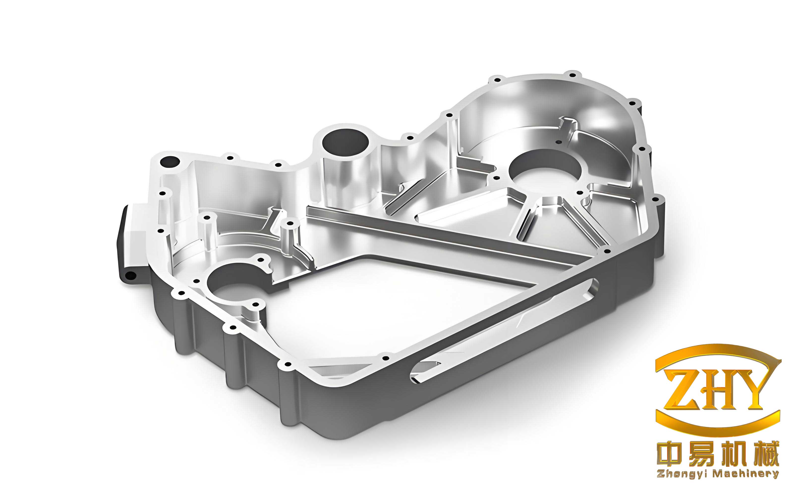
The differential housing, a quintessential example of a complex shell casting, serves as a safety-critical part in vehicle axles, transmitting torque under significant load. Its geometry, characterized by a flanged cylindrical body with intricate internal webs and pockets, presents distinct casting challenges. A detailed structural analysis is paramount. The primary dimensions are approximately 185 mm in diameter and 194 mm in height, with a nominal wall thickness of 20 mm and a single-piece weight of 8.2 kg. The material specification calls for ductile iron conforming to ASTM A536 grade 80-55-06, demanding a combination of strength and ductility.
| Parameter | Specification | Criticality for Shell Castings |
|---|---|---|
| Material | Ductile Iron (80-55-06) | High; requires controlled solidification to maintain nodule integrity. |
| Maximum Roughness (Non-machined surfaces) | ≤ 12.5 µm | High; surface quality is a hallmark of V-process shell castings. |
| Internal Defects | Zero porosity, shrinkage, slag inclusion | Absolute; directly impacts fatigue life of the shell casting. |
| Dimensional Tolerance (Length/Width) | CT6-CT8 | High; ensures proper assembly with mating components. |
| Dimensional Tolerance (Height) | CT9 |
The manufacturability analysis for this shell casting highlighted several foci. The thermal profile identified major hot spots at the junctions where the flange connects to the cylindrical body, precisely at the parting line. These areas are prone to shrinkage porosity if not managed. Furthermore, the V-process’s use of a dry, unbonded sand mold necessitates meticulous control of filling dynamics to prevent mold collapse or erosion. The goal was to achieve directional solidification favoring these hot spots while maintaining a rapid, tranquil fill. The philosophy for such shell castings is to adopt a “simultaneous solidification” approach augmented with localized chilling.
The foundational step in process design is selecting the parting plane. For this shell casting, the flange offered the most logical and practical location. This choice minimized undercuts, simplified pattern draw, and placed the parting line in a geometrically stable region. The mold arrangement was configured for a four-casting pattern per mold box to optimize productivity. The gating system is the circulatory heart of any casting process. For these shell castings, an open, non-pressurized, parting-line gating system was designed. The objective was to minimize turbulence and promote a smooth, progressive fill from the bottom of the cavity. The gating ratio was carefully calibrated as:
$$ \Sigma F_{sprue} : \Sigma F_{runner} : \Sigma F_{ingate} = 1 : 1.25 : 1.35 $$
This ratio ensures the ingates remain open until the end of pouring, preventing early aspiration of air into the mold cavity. The individual cross-sectional areas were calculated based on the total poured weight of 35.6 kg and a target fill time. The relationship between poured weight \( W \) (kg), fill time \( t \) (s), effective head height \( h \) (m), and total ingate area \( A_g \) (m²) can be approximated by the basic fluid flow equation:
$$ W = \rho \cdot A_g \cdot v \cdot t $$
$$ v = C_d \sqrt{2gh} $$
Where \( \rho \) is the molten iron density (~7000 kg/m³), \( v \) is the flow velocity, \( C_d \) is the discharge coefficient (~0.8 for ceramic-coated systems), and \( g \) is acceleration due to gravity. Solving for the required ingate area for a target fill time of 14 seconds and a head height of 0.3 m confirms the designed areas.
| Element | Quantity | Cross-Section Shape | Dimensions (mm) | Total Area (mm²) | Function |
|---|---|---|---|---|---|
| Sprue | 1 | Circular | Ø32 | 804 | Vertical delivery |
| Runner | 2 | Trapezoidal | Top:22, Bottom:26, Ht:21 | 1008 | Distribute metal |
| Ingate | 4 | Trapezoidal | Top:25, Bottom:29, Ht:10 | 1080 | Control entry into cavity |
To address the identified hot spots, graphite chills were precisely placed at the flange-body junctions on both the cope and drag sides. Graphite’s high thermal conductivity efficiently extracts heat, promoting rapid solidification in these volumes and eliminating shrinkage defects. Additionally, an overflow riser was positioned at the metal flow terminus for each shell casting cavity. This serves a dual purpose: it acts as a slag trap, collecting the first, possibly oxidized metal, and provides a pressure relief path for entrapped air, enhancing cavity fill. The final mold layout, with chills and overflows, is crucial for producing sound shell castings.
The V-process molding sequence demands rigorous control. My procedure began with heating a 0.08 mm thick EVA film until it achieved a perfectly drapable, glossy state. The vacuum level during film drawing and pattern covering was maintained between -0.025 and -0.035 MPa. A key insight for shell castings with deep draws is ensuring uniform film thickness without tearing. The coating application followed, using an alcohol-based zirconia coating with a density of 1.39 ± 0.03 g/cm³. The coating thickness \( \delta_c \) impacts both surface finish and gas permeability. An empirical relationship for sufficient barrier properties in V-process shell castings is:
$$ \delta_c > \frac{K \cdot P_{metal}}{S_{sand}} $$
Where \( K \) is a material constant, \( P_{metal} \) is the metal pressure head, and \( S_{sand} \) is the sand fineness. For our 70-140 mesh sand and iron pressure, a coating layer of 0.3-0.5 mm was applied. The dry sand filling and compaction using a modified jolting machine are critical. The achieved mold hardness consistently exceeded 90 on the scale, ensuring dimensional stability for the shell castings. The vacuum was held at -0.05 to -0.06 MPa throughout and during pouring. A specific innovation was the incorporation of a “pouring basin” or buffer at the base of the sprue in the drag to dissipate the initial momentum of the molten stream, protecting the fragile mold cavity from erosion.
| Process Stage | Parameter | Target Value/Range | Rationale |
|---|---|---|---|
| Molding | Film Heating & Forming Vacuum | -0.030 ± 0.005 MPa | Ensures crisp pattern replication on shell castings. |
| Mold Hardness (after compaction) | > 90 | Prevents mold wall movement during pour. | |
| Pouring | Pouring Temperature | 1340 ± 20 °C | Balances fluidity and minimized shrinkage tendency. |
| Mold Vacuum during Pour | -0.055 ± 0.005 MPa | Maintains mold rigidity; critical for shell castings. | |
| Pouring Time | 14 ± 2 s | Optimized from gating calculations to ensure quiescent fill. | |
| Total Metal Poured per Mold | 35.6 kg | Includes metal for gates, overflows, and castings. |
The solidification of shell castings in the V-process is influenced by the chilling effect of the vacuum-sealed dry sand and the explicit chills. The solidification time \( t_s \) for a section can be estimated using Chvorinov’s rule, modified for chill effects:
$$ t_s = B \left( \frac{V}{A} \right)^n \cdot f(C) $$
Where \( V/A \) is the volume-to-surface-area ratio (modulus), \( B \) and \( n \) are constants for the mold material, and \( f(C) \) is a function representing the chill efficiency factor (<<1 for graphite). The placement of chills at the high-modulus regions ensures that their solidification time falls below that of the surrounding thinner sections, effectively creating a directional solidification pattern toward the chill itself, thereby feeding the hot spot.
The production outcome unequivocally validated the process design for these shell castings. Visual inspection revealed a superb surface finish, with non-machined areas exhibiting a roughness significantly better than the 12.5 µm requirement, a direct benefit of the smooth plastic film and fine sand interface. Dimensional audits across multiple batches confirmed exceptional consistency. The length and width dimensions held tolerances within CT6 to CT8 grades, while the height, often more variable due to joint line effects, consistently achieved CT9. This level of precision for shell castings rivals that of more expensive investment casting processes.
| Quality Attribute | Measured Result | Specification | Status |
|---|---|---|---|
| Surface Roughness (Ra) | 6.3 – 10.5 µm | ≤ 12.5 µm | Exceeded |
| Internal Defects (X-ray & Sectioning) | None detected | Zero major defects | Conformed |
| Dimensional Accuracy (L/W) | CT7 on average | CT6-CT8 | Conformed |
| Dimensional Accuracy (H) | CT9 | CT9 | Conformed |
| Mechanical Properties (Sample Bars) | Tensile: 82 ksi, Elong: 7% | 80 ksi, 6% min | Exceeded |
Destructive sectioning of sample shell castings along the principal axis provided the most compelling evidence of internal soundness. The macrostructure was dense and uniform, completely free from gas holes, sand inclusions, shrinkage porosity, or macro-shrinkage cavities. The microstructural analysis in the chilled zones showed a refined graphite nodule count and pearlitic matrix, confirming the efficacy of the chilling strategy. The successful production of these high-integrity shell castings underscores a significant cost advantage. A detailed breakdown shows the V-process reduces the molding-related cost by approximately $800 per metric ton of castings compared to the prior resin sand method, stemming from the elimination of binders, reduced waste, and lower energy consumption for sand preparation.
Further discussion on the V-process for shell castings must consider the stability window of process parameters. The negative pressure \( P_{vac} \) is particularly crucial. It must be sufficient to maintain mold integrity against the metallostatic pressure \( P_{metal} = \rho g h \). The condition for stability is:
$$ P_{vac} > \frac{P_{metal}}{SF} $$
Where \( SF \) is a safety factor accounting for sand permeability and possible leaks. For our shell castings with a maximum head \( h \) of 0.25 m, \( P_{metal} \) is about 0.017 MPa. With a working \( P_{vac} \) of 0.055 MPa, the process operates with a comfortable margin. The interplay between pouring temperature and fill time also defines the quality of shell castings. Too low a temperature risks mistruns in thin sections; too high exacerbates shrinkage and mold reaction. The optimal window was determined empirically and validated by simulation, centering around 1340°C.
In conclusion, the systematic application of the V-process, grounded in principled gating design, strategic use of chills, and precise control of vacuum and thermal parameters, has proven exceptionally capable of producing high-performance shell castings like the differential housing. The methodology delivers superior surface finish, excellent dimensional repeatability, and cast-in integrity that eliminates downstream repair or salvage operations. This case study reinforces the V-process as a sustainable and economically compelling choice for manufacturing complex, high-duty shell castings across automotive and heavy machinery sectors. The lessons learned, particularly in managing thermal nodes and filling dynamics, are directly transferable to a broader family of shell castings, paving the way for wider adoption of this clean and efficient casting technology.