
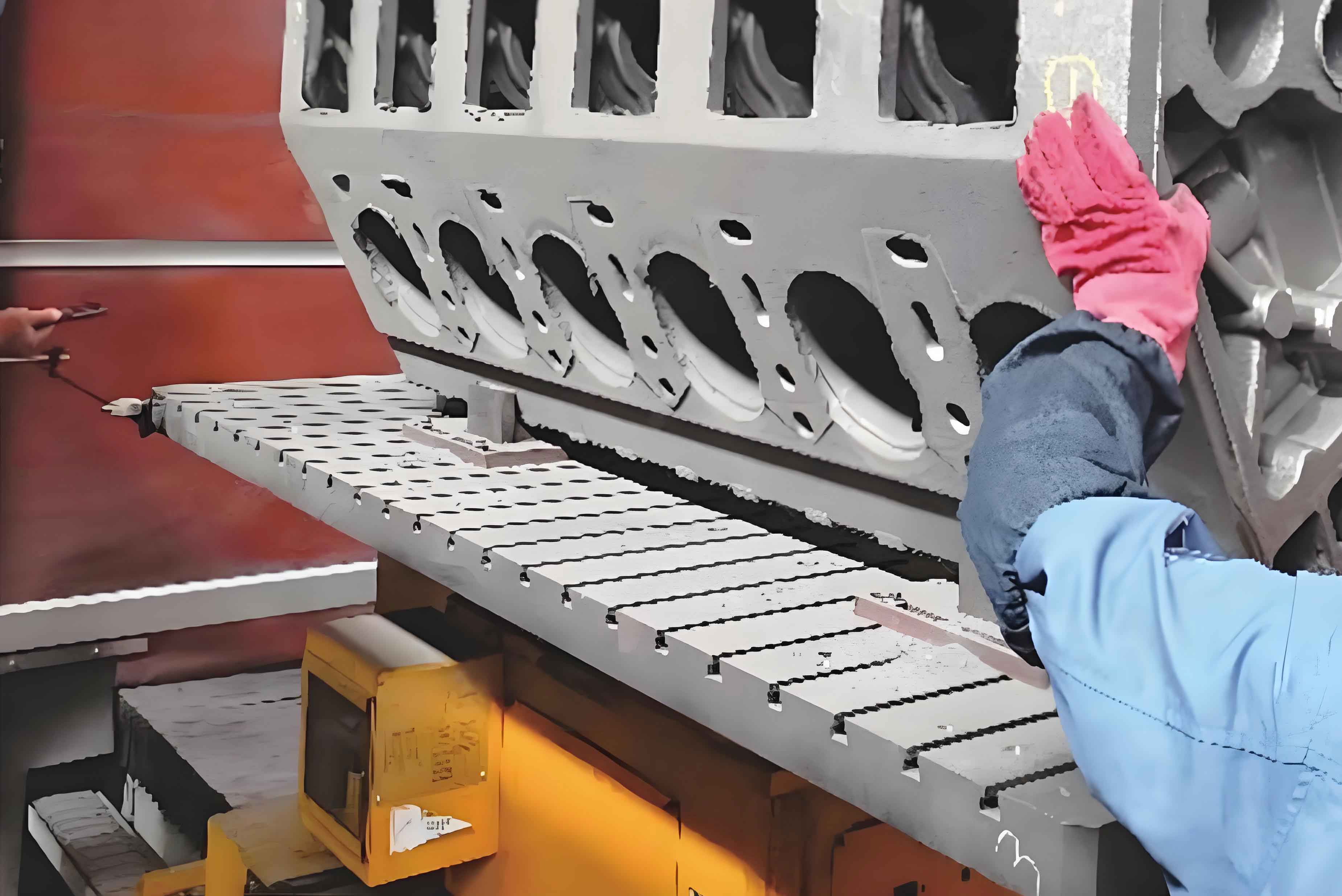
This study investigates the vibration characteristics of an in-line six-cylinder diesel engine cylinder block under operational and crankshaft deformation conditions. A finite element-based approach is developed to analyze natural frequencies, mode shapes, and vibration responses, providing critical insights for fault diagnosis and structural optimization.
1. Structural Dynamics and Working Principle
The engine cylinder block-piston-crankshaft system operates through coordinated motion of four-stroke cycles. The firing order (1-5-3-6-2-4) creates periodic excitation forces given by:
$$F(t) = \sum_{n=1}^{6} m_n r\omega^2 \cos(\omega t + \phi_n)$$
where \( m_n \) represents reciprocating mass, \( r \) is crank radius, and \( \phi_n \) denotes phase angles between cylinders.
2. Modal Analysis of Engine Cylinder Block
The free vibration equation for finite element analysis is expressed as:
$$M\ddot{x} + Kx = 0$$
Solving the eigenvalue problem \( \det(K – \omega^2 M) = 0 \) yields natural frequencies and mode shapes. Constrained modal analysis results are summarized below:
| Mode | Frequency (Hz) |
|---|---|
| 1 | 152.30 |
| 2 | 214.51 |
| 3 | 311.08 |
| 4 | 336.53 |
| 5 | 347.96 |
| 6 | 396.97 |
| 7 | 433.19 |
| 8 | 575.42 |
Maximum deformations occur at central cylinders and crankshaft regions, with vibration amplitudes following the relationship:
$$A_i = \frac{F_0}{\sqrt{(k – m\omega_i^2)^2 + (c\omega_i)^2}}$$
where \( A_i \) represents amplitude at \( i \)-th natural frequency \( \omega_i \).
3. Crankshaft Deformation Impact
Vibration responses under 0.1-0.5 mm crankshaft deformations were analyzed at eight monitoring points. Key results show:
| Condition | Max Displacement (mm) | Velocity (mm/s) | Acceleration (m/s²) |
|---|---|---|---|
| Normal | 0.288 | 0.572 | 0.573 |
| Deformed | 1.411 | 2.806 | 2.801 |
The vibration amplification factor \( \beta \) due to crankshaft deformation follows:
$$\beta = \frac{A_d}{A_0} = 1 + \frac{\Delta r}{r} \cdot \frac{\omega^2}{\omega_n^2 – \omega^2}$$
where \( \Delta r \) denotes crankshaft radial deformation, and \( \omega_n \) represents natural frequency.
4. Vibration Monitoring Strategy
Optimal sensor placement was determined through modal participation analysis:
| Position | Mode Participation (%) |
|---|---|
| Central Cylinder Top | 92.4 |
| Front Support | 67.8 |
| Crankshaft Bearing | 85.3 |
The engine cylinder block exhibits maximum vibration energy between 300-400 Hz, requiring vibration monitoring equipment with sampling frequency \( f_s \geq 800 \) Hz according to Nyquist criterion:
$$f_s > 2f_{\text{max}}$$
5. Conclusion
Finite element analysis reveals that crankshaft deformation amplifies engine cylinder block vibrations by 2-4 times, particularly at central cylinder regions (positions 2, 3, 6, 7). The identified natural frequencies (152.30-575.42 Hz) and mode shapes provide critical references for avoiding resonance conditions. This methodology enables effective fault diagnosis through vibration pattern recognition, with monitoring thresholds recommended as:
$$\text{Alert}: 0.35\,\text{mm}, \quad \text{Shutdown}: 0.50\,\text{mm}$$
The engine cylinder block analysis framework demonstrates significant potential for predictive maintenance applications in heavy-duty diesel engines.