
In my experience as a structural engineer specializing in large-span steel constructions, the integration of high-grade thick steel casting components with sliding supports presents a critical challenge in ensuring structural integrity and longevity. This process is particularly vital in projects like railway station roofs, where steel arch trusses span significant distances and must withstand dynamic loads. The welding of steel casting to sliding supports demands meticulous attention to material properties, thermal management, and procedural precision. Throughout this article, I will delve into the comprehensive welding process, emphasizing the importance of steel casting in modern infrastructure. I will utilize tables and formulas to summarize key parameters and theoretical aspects, ensuring a thorough understanding of the methodology. The repeated mention of steel casting underscores its centrality in achieving durable connections.
The project I refer to involves a railway station roof composed of steel arch trusses with an inverted triangular cross-section and an 83-meter span. The arch foot nodes, made from G20Mn5QT steel casting, are connected to sliding supports, which facilitate movement and load distribution. The welding of these steel casting elements to the sliding support’s upper plate, fabricated from G20Mn5 steel, is a high-stakes operation due to the thick sections and stringent quality requirements. Failure in this weld could compromise the entire truss system, leading to safety hazards. Therefore, I have developed a detailed welding protocol that addresses design, installation, and quality control, with steel casting at its core.
From a design perspective, the steel casting is pre-machined with a 45-degree bevel groove, 90 mm deep, to ensure full penetration welding. This preparation is crucial for achieving a Grade I weld, as per structural standards. The connection details, as illustrated in engineering drawings, highlight the need for precise alignment and robust welding. The sliding support, with a design compressive strength of 200 MPa, must be rigidly fixed during welding to prevent misalignment. In my approach, I prioritize pre-welding preparations, including the setup of protective enclosures to shield the weld area from environmental factors like wind and moisture, which could induce defects. The use of steel casting here is intentional due to its superior castability and mechanical properties compared to forged or rolled steel, allowing for complex shapes and enhanced stress distribution.
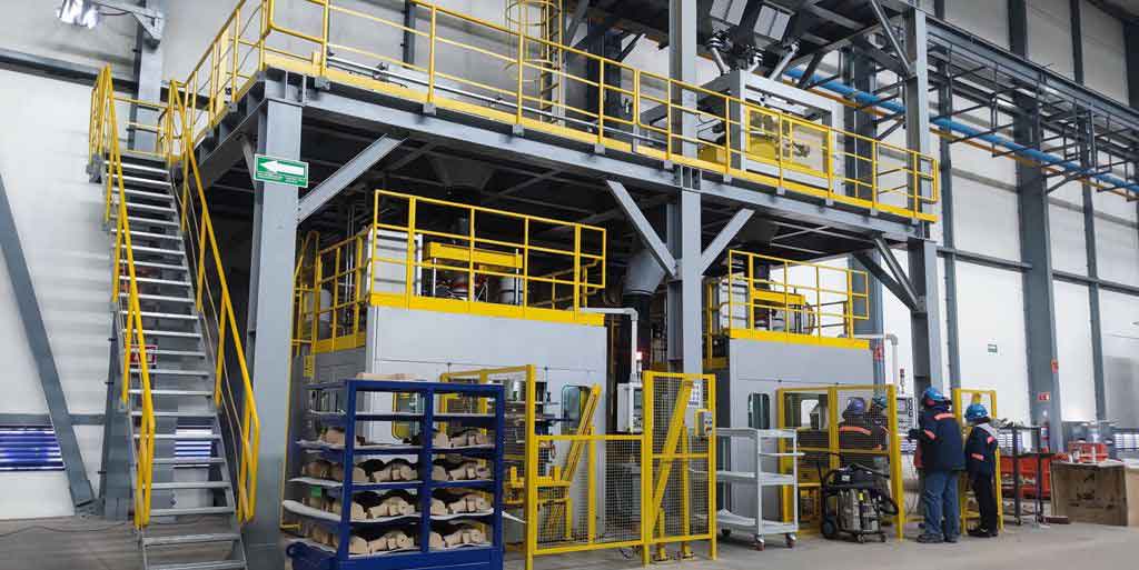
Preheating is a fundamental step in welding thick steel casting components, as it reduces the risk of hydrogen-induced cracking and minimizes residual stresses. Based on my calculations, the preheat temperature must be maintained between 180°C and 220°C, with an interpass temperature range of 150°C to 220°C. I employ electric heating equipment for uniform heat application across the groove and adjacent areas, covering a zone 1.5 times the material thickness. The thermal management can be expressed using the heat conduction formula: $$ \frac{\partial T}{\partial t} = \alpha \nabla^2 T $$ where \( T \) is temperature, \( t \) is time, and \( \alpha \) is thermal diffusivity. This ensures the steel casting reaches optimal weldability without overheating. The following table summarizes the preheating and interpass temperature parameters:
| Process Stage | Temperature Range (°C) | Duration (hours) | Remarks |
|---|---|---|---|
| Preheating | 180–220 | Until stable | Applied using electric heaters |
| Interpass Control | 150–220 | Continuous monitoring | Maintained via temperature gauges |
| Post-Weld Heating | 250–300 | 0.5 | For hydrogen removal |
| Insulation | Ambient to slow cool | 4 | Using asbestos-free materials |
The welding process itself involves gas metal arc welding (GMAW) with CO₂ as the shielding gas. I select CHW-50C6 filler wire, 1.2 mm in diameter, to match the base materials of the steel casting and support plate. The welding parameters are critical for controlling heat input and ensuring penetration. The heat input formula is: $$ Q = \frac{I \times V \times 60}{S} $$ where \( Q \) is heat input in J/mm, \( I \) is current in amperes, \( V \) is voltage in volts, and \( S \) is welding speed in mm/min. For the steel casting weld, I aim for a heat input between 1.0 and 1.5 kJ/mm to avoid excessive grain growth. The table below details the welding parameters for different layers:
| Weld Layer | Current (A) | Voltage (V) | Speed (cm/min) | Gas Flow (L/min) | Heat Input (kJ/mm) |
|---|---|---|---|---|---|
| Root Pass | 220–240 | 28–30 | 24–26 | 20–25 | 1.2–1.4 |
| Fill Passes | 240–260 | 30–32 | 26–28 | 20–25 | 1.3–1.5 |
| Cap Pass | 200–240 | 30–32 | 26–28 | 20–25 | 1.0–1.3 |
During execution, I assign two welders to perform symmetrical welding to balance thermal stresses and distortion. The welding sequence starts from the root and progresses outward, with each pass cleaned of slag and spatter. For the steel casting, I monitor dimensional accuracy using laser alignment tools, adjusting the welding order if deviations occur. The residual stress in the weld zone can be estimated using: $$ \sigma_r = E \alpha \Delta T $$ where \( \sigma_r \) is residual stress, \( E \) is Young’s modulus, \( \alpha \) is coefficient of thermal expansion, and \( \Delta T \) is temperature gradient. This emphasizes the need for controlled cooling. Post-weld, I immediately apply a post-heat treatment at 250–300°C for 30 minutes, followed by insulation for 4 hours to facilitate hydrogen effusion and stress relief. The diffusion of hydrogen can be modeled with Fick’s law: $$ J = -D \frac{\partial C}{\partial x} $$ where \( J \) is flux, \( D \) is diffusivity, \( C \) is concentration, and \( x \) is distance. This step is vital for preventing cold cracks in the steel casting.
Quality control is integral to the welding of steel casting components. After 24 hours of cooling, I conduct 100% ultrasonic testing (UT) to detect internal defects like porosity or lack of fusion. The acceptance criteria are based on AWS D1.1 standards, with any indication above threshold requiring repair. Additionally, I perform visual inspections for surface defects and dimensional checks using coordinate measuring machines. The mechanical properties of the weld, such as tensile strength and impact toughness, are verified through destructive testing on witness coupons. The relationship between weld quality and service life can be expressed as: $$ L = \frac{K}{\sigma_a^m} $$ where \( L \) is fatigue life, \( K \) is a material constant, \( \sigma_a \) is stress amplitude, and \( m \) is an exponent. This underscores the importance of flawless welding in steel casting applications.
In terms of material science, the steel casting used here, G20Mn5QT, offers a yield strength of over 350 MPa and good weldability due to its quenched and tempered microstructure. The carbon equivalent (CE) formula is: $$ CE = C + \frac{Mn}{6} + \frac{Cr + Mo + V}{5} + \frac{Ni + Cu}{15} $$ For this steel casting, CE is approximately 0.45, indicating moderate hardenability and necessitating preheat. Compared to conventional steel, steel casting allows for intricate geometries that reduce stress concentrations at the arch foot node. The sliding support, made from G20Mn5 steel, has similar properties to ensure compatibility. The table below compares the material properties:
| Material | Yield Strength (MPa) | Tensile Strength (MPa) | Elongation (%) | Impact Energy (J at -20°C) | Carbon Equivalent |
|---|---|---|---|---|---|
| G20Mn5QT Steel Casting | ≥350 | 500–700 | ≥18 | ≥27 | 0.40–0.50 |
| G20Mn5 Steel Plate | ≥355 | 470–630 | ≥22 | ≥27 | 0.42–0.52 |
From an installation perspective, I ensure the sliding support is temporarily fixed to prevent movement during welding. The steel casting is then positioned using detailed coordinates, with tolerances within ±2 mm. Welding distortion is mitigated through sequenced passes and real-time monitoring. The angular distortion \( \theta \) can be approximated by: $$ \theta = \frac{\alpha Q}{d \rho c} $$ where \( \alpha \) is thermal expansion coefficient, \( Q \) is heat input, \( d \) is plate thickness, \( \rho \) is density, and \( c \) is specific heat. For the thick steel casting, distortion is minimal due to the symmetric approach. After welding, I remove temporary fixtures using carbon arc gouging, followed by grinding to smooth the surface without damaging the base metal of the steel casting.
Environmental considerations also play a role in welding steel casting. In outdoor settings, I use protective shelters to control wind speed below 2 m/s, as per welding codes. The dew point is kept below -10°C to avoid moisture ingress, which could introduce hydrogen. The electrode drying process follows the equation: $$ H = H_0 e^{-kt} $$ where \( H \) is hydrogen content, \( H_0 \) is initial content, \( k \) is a constant, and \( t \) is drying time. This ensures low-hydrogen conditions for the steel casting weld. Furthermore, I implement non-destructive testing methods like magnetic particle inspection for surface cracks and radiographic testing for critical sections, though UT is primary for this thick-section steel casting.
The economic and safety implications of welding steel casting are significant. By optimizing parameters, I reduce rework rates and enhance productivity. The total cost function for welding can be modeled as: $$ C = C_m + C_l + C_e $$ where \( C_m \) is material cost, \( C_l \) is labor cost, and \( C_e \) is equipment cost. For steel casting, the upfront cost is higher than for fabricated steel, but the long-term benefits in durability justify the investment. In terms of safety, proper ventilation and personal protective equipment are mandatory to fume exposure during welding of steel casting components.
In conclusion, the welding of thick steel casting to sliding supports is a multifaceted process that demands expertise in metallurgy, thermal dynamics, and quality assurance. Through systematic preheating, controlled welding parameters, and rigorous inspection, I achieve robust connections that ensure structural performance. The repeated focus on steel casting in this discussion highlights its critical role in modern steel construction, enabling complex geometries and high load-bearing capacity. Future advancements may involve automated welding robots for steel casting applications, but the fundamental principles outlined here will remain essential. By adhering to these practices, engineers can confidently tackle similar challenges in large-span structures.