
In the machinery industry, spheroidal graphite iron, commonly known as ductile iron, is a widely utilized material due to its excellent mechanical properties, such as high strength and good ductility. However, during the production of large-scale components like diesel engine blocks, casting defects such as pores, slag inclusions, and cracks frequently occur. These defects can severely compromise the reliability and service life of the components. From a cost perspective, when defects are located in non-critical areas, welding repair is often employed to restore the integrity of the casting. As an engineer involved in materials processing, I have extensively studied various welding repair techniques for spheroidal graphite iron castings. This article presents a detailed first-person analysis of five distinct welding repair processes, focusing on their macroscopic morphology, metallographic structure, and mechanical performance. The goal is to provide a practical foundation for selecting appropriate repair methods, emphasizing the unique challenges posed by spheroidal graphite iron.
Spheroidal graphite iron is inherently difficult to weld, primarily due to issues like the formation of hard and brittle phases, such as cementite (white iron), in the fusion zone, and the propensity for cracking in the weld metal. The high carbon content and the presence of graphite nodules lead to significant microstructural changes during welding. The rapid cooling associated with many welding processes can result in hardened structures, making it challenging to match the hardness of the repair zone with the base metal. This mismatch can adversely affect machinability and performance. Therefore, successful welding repair of spheroidal graphite iron requires careful selection of welding methods, filler materials, and process parameters to minimize these detrimental effects.
In this study, we investigated five welding repair processes: manual arc welding, electro-spark deposition (EDM surfacing), thermal welding (oxygen-acetylene welding with preheating), patch resistance welding, and precision pulse arc welding. Each process operates on different principles, which influence the resulting microstructure and properties. Below, I describe each process in detail, followed by the experimental methodology and results.
Principles of Welding Repair Processes
Manual Arc Welding: This conventional process uses a consumable electrode coated with flux. An electric arc is struck between the electrode and the workpiece, melting both the filler metal and the base material. For spheroidal graphite iron, nickel-based electrodes (e.g., Z308) are commonly used due to their ability to mitigate crack formation and reduce hardness in the weld zone. The process is versatile but highly dependent on operator skill, and it often involves high heat input, leading to significant thermal effects.
Electro-Spark Deposition (EDM Surfacing): This is a low-heat-input process where a fine wire (typically nickel-chromium) is melted onto the substrate using controlled high-energy electrical discharges. The energy is localized, minimizing thermal distortion and heat-affected zone (HAZ) formation. It is suitable for repairing small surface defects but can be slow and may not achieve deep fusion.
Thermal Welding (Oxygen-Acetylene Welding with Preheat): This process uses a flame generated by burning oxygen and acetylene to melt the base metal and a filler rod (e.g., HS403 with flux). The key aspect is the preheating of the entire casting to around 550°C, followed by slow cooling. This reduces thermal gradients, preventing white iron formation and cracking. It is often considered the gold standard for quality but is logistically demanding and not feasible for all defect locations.
Patch Resistance Welding: This method involves using a specialized device to create a short-circuit at the repair site, generating intense localized heat (1800–2200°C) that melts a patch material (often iron filings from the base metal) onto the defect. It is a cold process with minimal HAZ, but the bond is primarily mechanical, and the repair may exhibit layered structures.
Precision Pulse Arc Welding: Also known as precision cold welding, this technique uses stored capacitive energy discharged as pulsed arcs between a tungsten electrode and the workpiece. The filler wire (high-nickel) is melted with minimal overall heat input, resulting in a metallurgical bond with negligible thermal impact on the spheroidal graphite iron base. It is operator-friendly and effective for precise repairs.
Experimental Methodology
The base material used was QT400 spheroidal graphite iron, with a nominal composition of approximately 3.6–3.8% C, 2.0–2.5% Si, and magnesium for nodularization. Specimens were prepared as per the dimensions shown in the original study, with a groove machined to simulate a defect. Each welding process was applied according to standard procedures, and post-weld samples were sectioned for analysis. Macroscopic examination was conducted visually, while metallographic samples were prepared by grinding, polishing, and etching with 4% nital. Hardness measurements were taken using a Vickers hardness tester, and tensile tests were performed on welded joints to evaluate mechanical integrity. The experimental parameters are summarized in Table 1.
| Welding Process | Equipment | Filler Material Composition (wt.%) | Key Parameters | Thermal Input Estimate |
|---|---|---|---|---|
| Manual Arc Welding | DC Power Source | Ni ≥95, C ≤1.0, Si ≤2.0, Fe ≤3.5 | Current: 90–120 A, Voltage: 22–28 V | High: $$ Q = \frac{V \times I \times t}{A} \approx 1.5 \text{ kJ/mm} $$ |
| Electro-Spark Deposition | EDM Surfacing Machine | Ni-Cr alloy wire | Pulse energy: 0.5–2 J, Frequency: 50–200 Hz | Very Low: $$ Q \approx 0.1 \text{ kJ/mm} $$ |
| Thermal Welding | Oxy-Acetylene Torch, Furnace | Fe ≥84, Si ≥6.0, Mn ≥0.5 with flux | Preheat: 550°C, Flame: Neutral, Post-heat: Slow cool | Moderate but controlled: $$ Q \approx 0.8 \text{ kJ/mm} $$ |
| Patch Resistance Welding | Defect Repair Machine | Iron filings from base metal | Pulse discharge: 1–3 ms, Voltage: 10–20 V | Extremely Low: $$ Q \approx 0.05 \text{ kJ/mm} $$ |
| Precision Pulse Arc Welding | Precision Welder | Ni ≥95 (high-nickel wire) | Pulse duration: 1–5 ms, Current: 50–150 A | Low: $$ Q \approx 0.3 \text{ kJ/mm} $$ |
The thermal input (Q) is estimated using the formula: $$ Q = \eta \frac{V \times I}{v} $$, where η is efficiency, V is voltage, I is current, and v is travel speed. For simplicity, we assume η=0.8 for arc processes and η=0.5 for others, with v adjusted based on observed deposition rates. These values illustrate the relative heat inputs, which critically influence the microstructure of spheroidal graphite iron.
Results and Analysis
Macroscopic Morphology
Manual arc welding produced a weld bead with some undercut and incomplete penetration at the root, primarily due to groove geometry and operator variability. Electro-spark deposition showed excellent surface conformity with no visible distortion of the base spheroidal graphite iron. Thermal welding yielded the most uniform and smooth appearance, with minimal color difference from the parent metal. Patch resistance welding exhibited a layered build-up, often with visible interfaces, while precision welding resulted in a clean, well-formed weld with slight undercut in some cases.
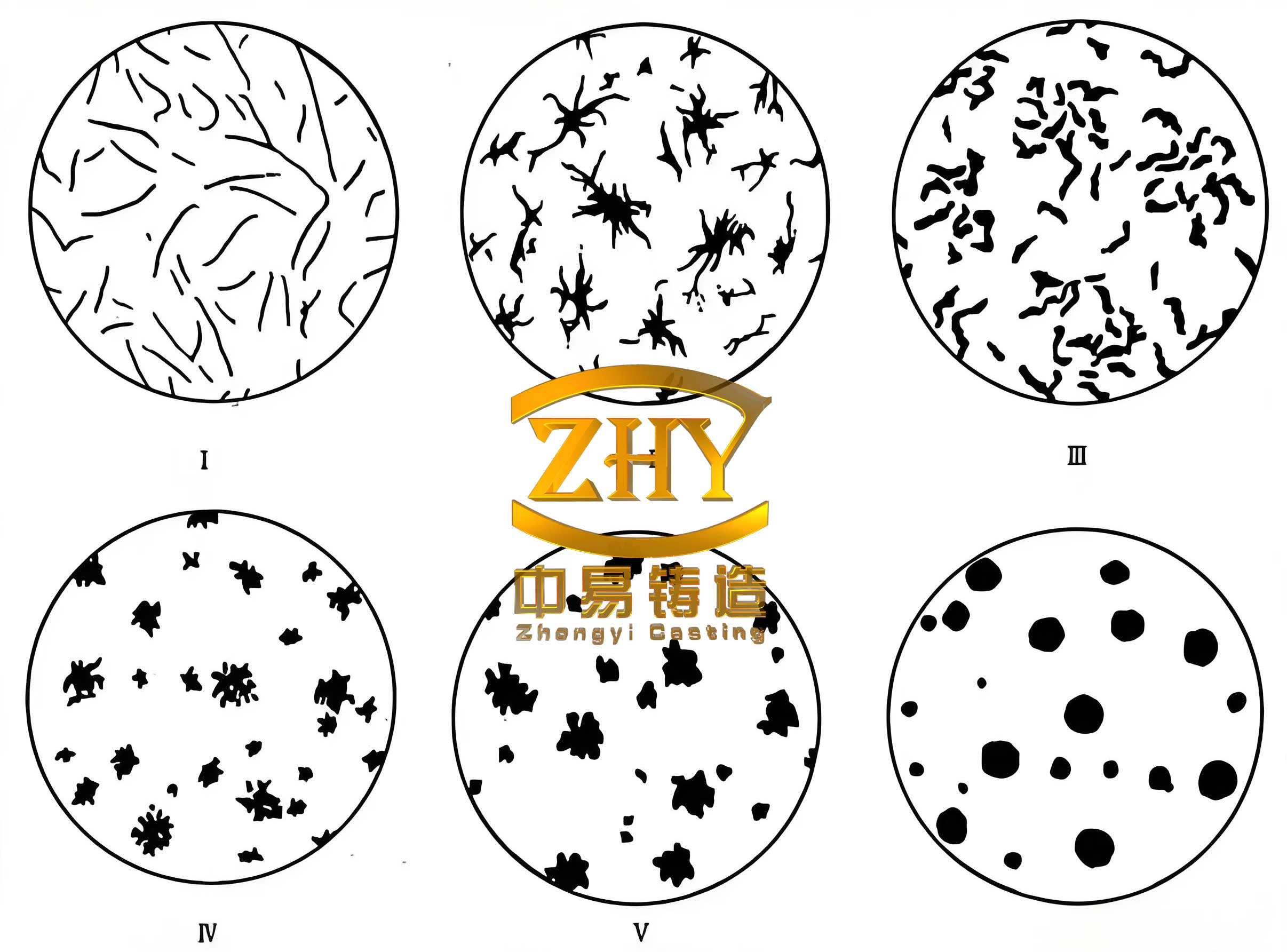
The image above illustrates a typical microstructure of spheroidal graphite iron, highlighting the graphite nodules in a ferritic matrix. This structure is sensitive to thermal cycles, and welding can alter it significantly.
Metallographic Structure
The metallographic analysis revealed distinct zones for each process. For manual arc welding on spheroidal graphite iron, the base metal showed ferrite and graphite nodules. The HAZ adjacent to the weld exhibited coarsened graphite, while the fusion line was sharp, and the weld metal consisted primarily of nickel-rich austenite with some carbides. The cooling rate here can be modeled as: $$ \frac{dT}{dt} = -k (T – T_0) $$, where k depends on process conditions. High cooling rates promote martensite or cementite formation.
Electro-spark deposition displayed a clear interface between the deposit and the base spheroidal graphite iron, with no discernible HAZ. The deposit had a fine, dendritic structure of nickel-chromium alloy. Thermal welding showed a gradual transition: the base metal remained largely unchanged, the fusion zone contained fine spheroidal graphite, and a decarburized layer (≈200 µm) of ferrite existed at the interface. The weld center had a fine gray iron-like structure with tiny graphite flakes. This is attributed to the slow cooling, which allows carbon diffusion, reducing the driving force for white iron formation. The kinetics can be described by Fick’s law: $$ J = -D \frac{\partial C}{\partial x} $$, where J is carbon flux, D is diffusivity, and C is concentration.
Patch resistance welding revealed a layered morphology with obvious boundaries between successive deposits, indicating limited fusion. Precision welding showed a metallurgical bond where the nickel-based filler melted into the spheroidal graphite iron, with some graphite nodules entrapped in the weld metal. There was no HAZ, preserving the base microstructure.
To quantify microstructural features, we measured nodule count and phase fractions using image analysis. Table 2 summarizes key observations.
| Welding Process | Fusion Zone Width (µm) | HAZ Width (µm) | Predominant Phases in Weld | Graphite Morphology in HAZ | Hardness at Interface (HV) |
|---|---|---|---|---|---|
| Manual Arc | 100–300 | 500–1000 | Austenite, Carbides | Coarsened | 250–350 |
| Electro-Spark | 50–150 | None | Ni-Cr Dendrites | Unaffected | 200–300 (deposit) |
| Thermal Welding | 200–500 | 100–200 | Ferrite, Fine Graphite | Fine Spheroidal | 150–200 |
| Patch Resistance | N/A (layered) | None | α-Fe, Cementite | Unaffected | 180–250 |
| Precision Welding | 50–200 | None | Ni-Austenite | Unaffected | 220–280 |
The hardness values correlate with microstructural phases. For instance, high hardness in manual arc welds indicates martensite or carbides, while lower hardness in thermal welding suggests ferrite dominance. The hardness profile can be modeled using a relationship like: $$ H = H_0 + k \cdot \sqrt{C} $$, where H is hardness, H_0 is base hardness, k is a constant, and C is carbon in solution.
Mechanical Performance
Tensile tests were conducted on specimens from manual arc, thermal, and precision welding processes, as patch resistance and electro-spark deposition did not allow standard specimen preparation. The results, averaged over two samples each, are shown in Table 3. The strength of spheroidal graphite iron base metal is typically around 400 MPa for QT400.
| Welding Process | Ultimate Tensile Strength (MPa) | Fracture Location | Estimated Joint Efficiency (%) |
|---|---|---|---|
| Manual Arc Welding | 55.5 | Weld Metal | 13.9 |
| Thermal Welding | 262.5 | Base Metal near HAZ | 65.6 |
| Precision Welding | 128.0 | Weld Metal | 32.0 |
The joint efficiency is calculated as: $$ \text{Efficiency} = \frac{\sigma_{\text{weld}}}{\sigma_{\text{base}}} \times 100\% $$, where σ is tensile strength. Thermal welding achieved the highest strength due to favorable microstructure, while manual arc welding suffered from brittle phases. Precision welding offered a balance, with moderate strength and minimal heat input. For patch resistance and electro-spark deposition, qualitative assessments indicate very low strength, suitable only for non-structural repairs.
Fractography revealed that manual arc welds failed via quasi-cleavage in the hard weld metal, thermal welds failed in the base metal due to strain localization, and precision welds showed mixed modes. The fracture toughness can be related to microstructure using models like: $$ K_{IC} = \sigma_y \sqrt{\pi a} $$ for critical flaw size a, but detailed analysis was beyond this study’s scope.
Discussion on Process Selection
Choosing a welding repair process for spheroidal graphite iron depends on defect size, location, required mechanical properties, and operational constraints. Based on our findings, thermal welding is optimal for high-integrity repairs where preheating is feasible, as it minimizes harmful phases and provides good strength. However, for on-site or localized repairs, precision welding is excellent due to its cold process nature and decent metallurgical bonding. Manual arc welding requires skilled operators and is prone to defects, making it less reliable. Electro-spark deposition and patch resistance welding are best for cosmetic or superficial defects without load-bearing requirements.
The microstructural evolution in spheroidal graphite iron during welding can be predicted using phase transformation diagrams. For example, the time-temperature-transformation (TTT) diagram for ductile iron can be adapted to estimate phases formed at different cooling rates. The cooling rate (CR) can be approximated by: $$ CR = \frac{2\pi k (T – T_0)^2}{Q} $$, where k is thermal conductivity. For spheroidal graphite iron, a CR below 10°C/s typically avoids white iron, which is achievable in thermal welding but not in fast processes.
Furthermore, the dilution ratio, which affects weld composition, is critical. For a process with filler material, dilution D is given by: $$ D = \frac{A_{\text{base}}}{A_{\text{base}} + A_{\text{filler}}} \times 100\% $$, where A is cross-sectional area melted. High dilution can lead to excessive carbon pickup in the weld, promoting carbides. In our tests, thermal welding had moderate dilution, while precision welding had low dilution, preserving the nickel-rich weld metal properties.
Conclusion
In this comprehensive study, we evaluated five welding repair processes for spheroidal graphite iron castings. Thermal welding (oxygen-acetylene with preheat) produced the best overall results in terms of microstructure homogeneity and mechanical strength, making it suitable for critical repairs. Precision pulse arc welding offered a viable cold-process alternative with good bond integrity and minimal thermal damage. Manual arc welding, while common, resulted in brittle welds with low tensile strength due to high heat input and rapid cooling. Electro-spark deposition and patch resistance welding were effective for surface-level repairs but lacked structural capability. The key takeaway is that the choice of repair method must align with the specific requirements of the spheroidal graphite iron component, considering factors like defect severity, location, and performance expectations. Future work could explore hybrid processes or advanced filler materials to further enhance weld properties in this challenging material.
Throughout this analysis, the term spheroidal graphite iron has been emphasized to underscore the material’s unique characteristics and its sensitivity to thermal processes. By understanding these nuances, engineers can make informed decisions to extend the life of costly castings, ensuring reliability in demanding applications. The tables and formulas provided here serve as a concise reference for comparing processes and predicting outcomes based on fundamental principles.